EasyManua.ls Logo

Konica Minolta SD-511 User Manual

Konica Minolta SD-511
11 pages
To Next Page IconTo Next Page
Page #1 background imageLoading...
Page #1 background image
E-1
INSTALLATION MANUAL
A3ER-9550-00
SD-511 Saddle Stitcher
Caution:
Lifting the machine in an awkward position or
transporting it in a poorly balanced position could
result in personal injury. When transporting the
machine, assign an adequate number of persons
to the job and ensure that each person can take a
good position of not being excessively loaded.
(mass: approx. 23 kg (50-11/16))
I. Accessory parts
Note:
This manual provides the illustrations of the acces-
sory parts and machine that may be slightly different
in shape from yours. In that case, instead of the
illustrations, use the appearance of your machine to
follow the installation procedure. This does not
cause any significant change or problem with the
procedure.
No. Name Shape Q’ty
1. Exit tray
1
2. Exit tray cover
1
3. Exit lever
1
4. Guide plate
1
5. Rail (Right)
without hook
1
6. Rail (Left)
with hooks
1
7. Screw
6
A3ERIXC001DA
A3ERIXC002DA
A3ERIXC003DA
A3ERIXC004DA
A3ERIXC005DA
A3ERIXC006DA
9654
8. Installation
manual
1
set
After unpacking, be sure to get rid of the
packaging materials and keep them out of
the reach of children.
Putting the head in the plastic bag
involves danger of suffocation.
No. Name Shape Q’ty
4980IXC019DA
Applied Machine: FS-534
Question and Answer IconNeed help?

Do you have a question about the Konica Minolta SD-511 and is the answer not in the manual?

Konica Minolta SD-511 Specifications

General IconGeneral
Compatible Devicesbizhub PRESS C1070/C1060/C1100, bizhub PRESS C1070P/C1060P, bizhub PRESS C71hc
Paper SizesA5
Stapling PositionsCorner
Stapling CapacityUp to 50 sheets
Saddle-stitch CapacityMax. 20 sheets
Fold TypesHalf-fold, Tri-fold

Summary

Accessory Parts

Installation Procedures

Prepare Machine and Unpack Accessories

Turn off the machine, unplug power, unpack accessories from carton, and remove protective materials.

Attach Exit Lever and Cover

Remove pin from exit lever, then attach lever to exit tray cover using the pin.

Remove Finisher Components

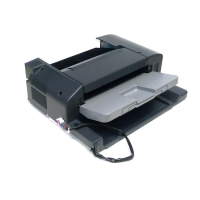
Remove finisher if mounted, open front door, and remove front cover by unscrewing six screws.

Adjust Stapler Unit Position

Move stapler unit to rear by turning dial if positioned forward.

Attach Guide Plate

Remove C-clip from guide plate, open guide plate, and attach it to the finisher using the C-clip.

Remove Finisher Cover

Remove seven screws holding the cover, disconnect the connector, tilt, and remove the cover.

Attach Rails

Align and attach left and right rails to the finisher plate using two screws each.

Connect Components and Attach Tray Cover

Plug in two connectors and attach the exit tray cover to the finisher with seven screws.

Mount Saddle Unit to Rails

Pull left rail out, lift saddle unit, and fasten it to the left rail by fitting tabs into slots.

Mount Saddle Unit to Right Rail

Pull right rail out, fit saddle unit boss into rail's positioning hole, and attach with one screw.

Secure Saddle Unit and Connect Pantograph

Insert saddle unit pantograph hooks into rear finisher holes and secure with a screw.

Complete Finisher Assembly

Close guide plate and front door, then place the exit tray on the finisher.

Mount Finisher to Machine and Power On

Mount the finisher to the machine, plug in the power cord, and turn on the machine.

Adjustments

Half-Fold Skew Adjustment

Adjust the guide plate assy forward or backward based on crease deviation.

Half-Fold Position Adjustment

Adjust the half-fold position using the service mode screen based on crease deviation.

Center Staple Position Adjustment

Adjust the center staple position using the service mode screen based on staple deviation.

Tri-fold Position Adjustment

Adjust first and second tri-fold positions using service mode based on paper measurements.
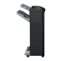
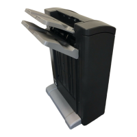
Related product manuals