SAFETY INSTRUCTIONS
1. COMPONENTS
After unpacking the item, please perform a visual inspection in
order to determine whether all parts are present and, as far as
can be seen, undamaged .
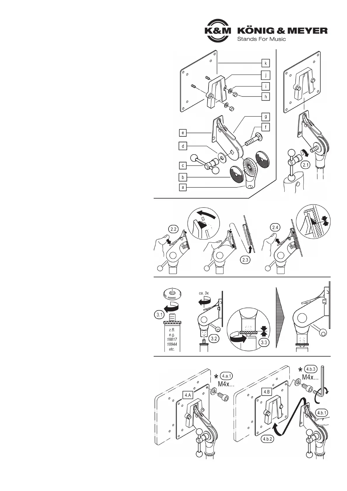
SWIVEL JOINT:
a
swivel head 3/8" (5/8"), b rubber washer diameter 40 mm (2x),
c T-bar locking screw M8, d washer diameter 24 mm, e swivel joint,
f carriage bolt M8 x 30 mm, g quick release lever
ADAPTER PLATE:
h cap nut M5, i washer diameter 10 mm, j connecting plate,
k adapter plate
2. ASSEMBLY of the 19685
2.1 Pull the bag off the thread; remove the T-bar locking screw c
2.1 and screw it onto the thread.
2.2 Operate the upper lever g of the quick-release fastener.
2.2 This causes the mandrel to retract.
2.3 Now push the plug-in plate of the swivel joint e into
2.3 the connecting plate j as far as it will go.
2.4 Release lever g, thereby causing the mandrel to enter
2.4 the connecting plate clearance j and secure the connection.
2.4 NOTE:
2.4 The adapter plate k can be removed only
2.4 by operating the lever g again.
3. MOUNTING on the HOLDER/STAND
3.1 Turn the knurled washer on the stand as far as it will go
3.1 on the threaded bolt.
3.2 Now also screw the swivel joint on: approx. 3 turns.
3.3 Turn the knurled washer back again so that it is clamped
3.3 to the swivel joint is free from play.
4. ATTACH SCREEN to ADAPTER PLATE
There are two possible approaches to this:
4.A Leave the adapter plate on the swivel joint…
4.a.1 …and screw them together with the screen.*
4.B Remove the adapter plate from the swivel joint;
4.b.1 press the lever g of the quick-release fastener to do this
4.b.2 pull off the adapter plate k…
4.b.3 …and screw them to the screen*
4.b.4 Then reconnect the adapter plate k (together with the screen)
to the swivel joint e - see Chapters 2.2 - 2.4.
* The mounting is done by means of four M4 × … screws. However,
* these are not included in the scope of delivery because their
* length depends on the dimensions of the respective screen.
Thank you for choosing this product. Please read and follow these instructions
carefully before setting up and operating this product. They inform you about all
the important steps involved in setting up and handling. We recommend that you
also keep them for future use.
ASSEMBLY INSTRUCTIONS
- Please observe the information in these installation instructions
- Also observe the safety instructions and instructions of products
- involved (stand, screen)
- Max. load-bearing capacity: 5 kg
- The stand used must be able to safely support the load of
- the adapter and the screen; this applies to both the load-
- bearing capacity and the stability of the stand (sufficiently
- large base diameter)
- The stand base must be load-bearing and level
- Ensure that the screw connections are tight, and check
- them at regular intervals
- Do not swivel the screen into an overhead position because
- the plug-in connection may loosen independently as soon as
- the latching lever is released. See Figure: 6.3.4.1
- Protect from moisture
- Damaged parts must be replaced
1. COMPONENTS
2. ASSEMBLY
3. MOUNTING on the HOLDER/STAND
4. ATTACH SCREEN to ADAPTER PLATE
19685 Adapter for screens
- Adapter for attaching a small LCD/LED LCD/LED screens on a stand e.g.:
- Keyboard stands:
- - 18810/20 »Omega« (via Universal holder 18807, 18817)
- - 18840/60 »Spider Pro« (directly or via 18872, 18873),
- - 18930/33/90/97 X-Ständer (via Universal holder 18944)
- - 18950/53 folding tables (via Universal holder 18807, 18817)
- Equipment stand:
- - 18826 (via Universal holder 18944)
- Microphone stands (not on the boom arm):
- - depends on stability (best to carry out tests)
- - with stand connection thread:
- - 3/8" (Item no.19685-300-55) as well as
- - 5/8" (Item no.19685-500-55)
- VESA adapter plate: Hole spacing 75 x 75 mm and 100 x 100 mm
- Load-bearing capacity max. 5 kg
- Continuously adjustable in direction (360°) and inclination
- Adapter plate can be attached and removed quickly and easily
via prismatic connection
 Loading...