EasyManua.ls Logo

KONVEKTA FR4 - User Manual

KONVEKTA FR4
19 pages
Print Icon
To Next Page IconTo Next Page
Loading...
Konvekta AG
Konvekta AGKonvekta AG
Konvekta AG
Am Nordbahnhof 5
34613 Schwalmstadt
Germany
+49 ( 0 ) 66 91 / 76 – 0
+49 ( 0 ) 66 91 / 76 - 200
Info@konvekta.com
www.konvekta.com
Instructions for install
Instructions for installInstructions for install
Instructions for installa
aa
ation and
tion and tion and
tion and
se
sese
ser
rr
rvice
vicevice
vice
for control unit
for control unitfor control unit
for control unit
FR4
FR4FR4
FR4
12
12 12
12 -
--
- 24 Volt DC
24 Volt DC 24 Volt DC
24 Volt DC
ID#: 110013962AA
ID#: 110013962AAID#: 110013962AA
ID#: 110013962AA-
--
-a02
a02a02
a02
Valid from 08
Valid from 08Valid from 08
Valid from 08/200
/200/200
/2008
88
8
Question and Answer IconNeed help?

Do you have a question about the KONVEKTA FR4 and is the answer not in the manual?

Summary

Technical Data of Control Unit

General Description of the Control Unit

LED Display

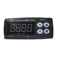
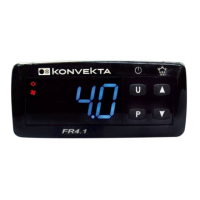
The display shows information about the current control mode via different LED indicators.

Programming Menu

The programming menu includes all parameters of the unit, accessible at the Service level.

Connecting and Safety Instructions

Safety Instructions

Important warnings regarding unit connection, ambient conditions, housing, sensor installation, and electrical connections.

Switching-on the Unit

Switching-on via Button [U]

Details pressing the [U] button for 3 seconds to switch on the unit and display readings.

Faults - Indications and Signals

Fault Indications

Explains how faults are indicated by blinking display and lists fault codes like E1 and E2.

Adjustment of Parameters in the Menu

Changing Defrost Interval Parameter

Step-by-step guide on how to change a parameter like defrost interval, including password entry.

Conversion for Recirculated Air Defrosting

Details parameter changes required for converting to recirculated air defrosting or replacing older units.

Conversion to Cooling with Hot Gas

ATTENTION: FunC Parameter Change

Warning about changing the 'FunC' parameter to 'nr' only if a fluid extractor is installed.

Control of Defrosting

Configuration with FR 4 Copy-Key

Upload Configuration to Copy-Key

Steps to transmit configuration from FR4 to FR4 copy-key, including dip switch settings and LED signals.

Download Configuration from Copy-Key

Steps to transmit configuration from FR4 copy-key to another FR4 unit, checking LED signals.

Logic and Control Conditions

Cooling and Hot Gas Defrosting

Explains the logic for cooling and hot-gas defrosting, detailing compressor, fan, and DEF status.

Cooling and Recirculated Air Defrosting

Details the logic for cooling and recirculated air defrosting, referencing parameter changes.

Neutral Zone (Cooling + Heating with Hot Gas)

Explains neutral zone logic for cooling, heating, and hot-gas defrosting, referencing parameter changes.

Connection Diagram and Parameter Chart

Connection Diagram

Provides a visual diagram showing output and input connections for the control unit.

Parameter Chart (Group SP)

Lists parameters related to setpoints (Group SP) with their descriptions, ranges, and default values.

Defrosting Control Parameters (Group dEF)

Defrosting Mode Selection (dtyp)

Defrosting mode parameter, specifying electrical, hot air, or recirculated air defrosting.

Compressor Protection Parameters (Group PrC)

KONVEKTA FR4 Specifications

General IconGeneral
BrandKONVEKTA
ModelFR4
CategoryControl Unit
LanguageEnglish

Related product manuals