40
Other applications
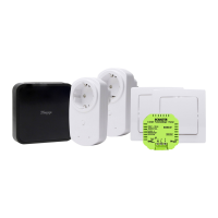
Description Connection of the universal radio transmitter to potential-free con-
tacts, e.g. relays, contactors, remote-control switch, motion detector, …
Application Individual control of one or several radio receivers.
Connectivity Up to two potential-free contacts can be connected to a universal
radio transmitter.
DIP switch
Setting
Depending on the potential-free contact‘s mode of operation (switch-
ing or inching), select mode A or B.
Mode of operation, page 30
Pinning diagram
(page 31)
Depending on the potential-free contact‘smode of operation (switching
or inching), carry out the pin assignment.
Pinning diagram, page 31
LED signalling With every signal emission, the universal radio transmitter‘s LED
flashes shortly.
MInstallation possibility
Installation in a flush-mounted box
The universal radio transmitter can be in-
stalled behind a flush-type switch, pushbut-
ton or shutter switch. A flush-mounted box of
at least 60 mm depth must be used.
Installation in a distribution board
In the event of applications outside of a
flush-mounted box, sucient safety guards
against accidental contact must be provided.
BLUE ELECTRIC installations
The universal radio transmitter can be in-
stalled in a surface-type enclosure of a Kopp
BLUE ELECTRIC switch or pushbutton behind
the switch base.
 Loading...