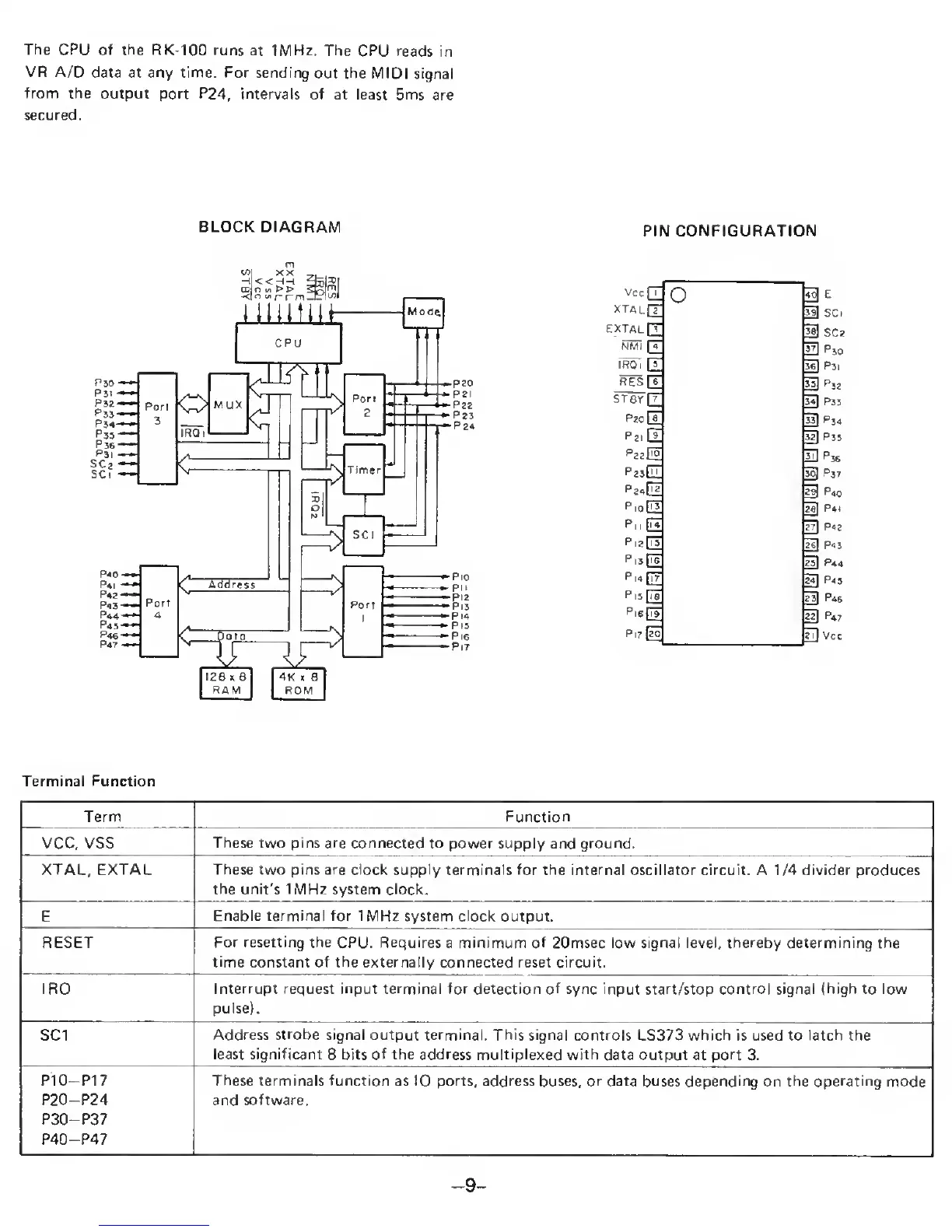
The CPU of the RK-100
runs
at
1MHz.
The CPU reads
in
VR A/D
data at any time. For sending
out the MIDI
signal
from the
output port P24, intervals of
at least 5ms
are
secured.
BLOCK DIAGRAM
PIN CONFIGURATION
Vccjl
O
xtau[T
extalQ;
NMi
13
^
13
ST8y[T
PziH
PzzDo
PzjGI
P,oQ3
p|i
[3
pizdl
P|3
[is
P|«[T7
Pi5
[ia
Pis[3
PitIzo
sc
El
Pso
5sl
P3I
Terminal Function
Term Function
VCC, VSS
These two pins are connected to
power supply and ground.
XTAL, EXTAL These two pins are clock supply terminals for
the
internal oscillator
circuit. A 1/4 divider produces
the unit's 1MHz system clock.
E
Enable terminal for 1
MHz system clock
output.
RESET
For resetting the
CPU.
Requires
a
minimum of 20msec low signal level, thereby determining the
time
constant of the externally connected reset circuit.
IRQ Interrupt request input terminal for detection of sync input start/stop control signal (high to low
pulse).
SCI
Address
strobe
signal output terminal. This signal controls
LS373 which is used to latch the
least significant
8
bits of the address multiplexed
with data output
at
port 3.
P10-P17
P20-P24
P30-P37
P40-P47
These
terminals function as
10
ports, address
buses,
or
data buses depending on the operating mode
and software.
-
9
-
 Loading...