VM-2HDT, VM-3HDT Quick Start
VM-2HDT, VM-3HDT Quick Start Guide
This guide helps you install and use your VM-2HDT, VM-3HDT for the first time.
Go to www.kramerav.com/downloads/VM-2HDT, VM-3HDT to download the latest user manual and check if
firmware upgrades are available.
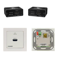
Step 1: Check what’s in the box
VM-2HDT or VM-3HDT HDBT DA/Extender
Step 2: Get to know your VM-2HDT, VM-3HDT
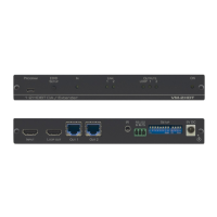
This section defines the VM-3HDT. VM-2HDT is identical but has 2 HDBT OUT connectors (OUT 1 and OUT 2).
PROGRAM Mini USB Connector
Use to send RS-232 commands.
Connect to a PC to perform firmware upgrades (via K-Upload) and work with the
EDID Designer. K-Upload and EDID Designer can be downloaded from our Web site
at: www.kramerav.com/support.
To use the mini USB port, you need to download and the Kramer USB driver from our
Web site at: www.kramerav.com/support/product_downloads.asp and install it.
Press to capture one of the output EDIDs or the default EDID to the input EDID.
Lights when an active input signal is detected.
Lights when a link is established with the receiver (VM-2HDT: 1 to 2).
OUTPUT LEDs (LOOP and 1 to
3)
Lights when a remote active output acceptor (sink) is detected on the LOOP or
HDBaseT receiver that is connected to the output (VM-2HDT: LOOP and 1 to 2).
Flashes when a non-HDCP acceptor is connected to the output and the input is
HDCP-encrypted (the content is displayed for only a few seconds).
Lights when the unit receives power.
Connects to the HDMI source.
Connect to a local monitor or a daisy-chained distributor, for example, a VM-4HDT.
HDBT OUT Connectors (1 to 3)
Connect to an HDBT acceptor, for example TP-580R (VM-2HDT: 1 to 2).
Connect an IR sensor for sending IR signals to a remote device (for example, a
projector connected to an HDBT receiver). Or
Connect an IR emitter (attached to a local device) for receiving IR signals from the
device’s IR remote control via HDBT.
RS-232 3-pin Terminal Block
Connect to a serial controller to control a remote device that is connected to the RS-
232 port of the HDbaseT receiver.
Used to set the IR and RS-232 command behavior.
Always keep all four DIP-switches UP (off).
Connects to the 5V DC power supply.