Table 1 and Table 2 define the front and rear panels of the VM-30AV and the
VM-30AVB, respectively.
Table 1: Front Panel VM-30AV and VM-30AVB 1:3 Audio/Video DA Features
# Feature Function
1 POWER Switch Illuminated switch supplying power to the unit
2 AUDIO LEVEL Knob Adjusts the audio output signal level
3 EQ. Trimmer Adjusts
1
the video EQ. (equalization) compensation
4
VIDEO
OUT
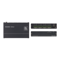
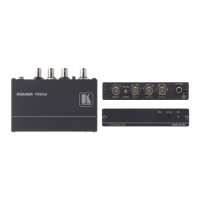
VM-30AV: RCA Connectors
VM-30AVB: BNC Connectors
Connects to the video acceptor (from 1 to 3)
7 INPUT (L) Connects to the left audio source
8 INPUT (R) Connects to the right audio source
9 OUT (L) Connects to the left audio acceptor (from 1 to 3)
10
AUDIO RCA
Connectors
OUT (R) Connects to the right audio acceptor (from 1 to 3)
11 12 VDC +12V DC connector for powering the unit
5 Using Your Audio/Video DA
Section 5.1 describes how to connect a VM-30AV/B
2
. Section 5.2 describes
how to configure a 1:3 Audio/Video DA for component video (YUV) or
RGB. You can also use the VM-30AV/B, with its very high frequency, to
process SDI (serial digital interface) video.
5.1 Connecting your VM-30AV/B
To connect
3
the VM-30AV/B 1:3 Audio/Video DA, as the example in Figure
3 illustrates, do the following:
1. Connect a composite video source (for example, a composite video player) to
the VIDEO INPUT connector
4
and to the left and right AUDIO INPUT RCA
connectors.
2. Connect
5
the 3 VIDEO OUT connectors
4
and the left and right AUDIO OUT
RCA connectors to the audio video acceptors (for example, composite video
recorders).
1 Insert a screwdriver into the small hole and carefully rotate it, to trim the appropriate level
2 From this section on, both machines are referred to as VM-30AV/B
3 Switch OFF the power on each device before connecting it to your VM-30AV/B. After connecting your VM-30AV/B,
switch on its power and then switch on the power on each device
4 RCA connectors for VM-30AV and BNC connectors for VM-30AVB
5 As required. Not all the outputs need to be connected