Additional parameter is selection of controller work mode (air/water). In respect of parameter’s
character it should be set only once for given installation, it is not included in menu with other para-
meters. So to preclude accidental change of parameter it can be changed by entering to its setting
after realization of proper procedure. During exit from power mode three octants are displayed on
the display for a moment.
During this time press button.
Such sequence will cause entering to selection of controller work mode. With up and own arrows we
choose one option H2O for replace with water jacket and air for replace with air heating.
We conrm our choice with button or we leave it without conrmation .
Additional functions of controller:
- Throttle’s emergency closing - in case of no voltage the controllers closes throttle, signalizes emer-
gency situation and turns o automatically;
- Protection from freezing – for controllers working with set work mode to H2O, protection from
freezing is activated. It consists in permanent monitoring of CO circulating liquid temperature and in
case of temperature fall below 5°C automatic turning on the pump in purpose to avoid installation
freezing;
- Automatic exit from power mode – despite of entering into power mode the controller controls
temperature and in case of detecting increase of temperature while replace kindling it automati-
cally goes to normal work mode.
Errors reported by controler:
Controller detects and displays errors related with temperature measurement:
- exceeding top scope (divergence on temperature sensor input)
- exceeding down scope (short-circuit on temperature sensor input)
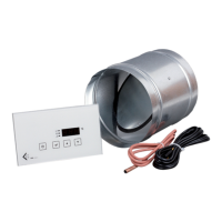
Controller instalation:
Following elements come under composition of supplied device:
1. Controler’s electronics in standard under-plaster box
2. Throttle with servo-mechanism
3. Temperature sensor on cable
4. Cable with connection to throttl
Controller installation should be began from proper assembly of throttle and temperature sensor
and supplying cables to place of steering panel assembly. In this place under-plaster box should be
assembled, it constitutes electrical part casing. Electronics is supplied from variable voltage 230V.
It is recommended that controller’s power supply should be conected through switch on fuse-board,
what will signicantly facilitate usage of controller. In case of replace with water jacket also the cable
supplying CO circulating pump should be connected to the controller. After preparing all cables
connect them to the controller according to scheme:
8
Ar This parameter determines whether the position of the throttle will be set automatically
depending on the temperature sensor. Symbol „ ” means inclusion, and the symbol „ ” shows
o of an automatically adjusts the throttle position. When the auto driver is o the controller
displays the status of the display by inammation of the rst dot from the right hand side
on the bottom.The controller automatically turns on automatically adjusts the throttle when
approaching the temperature sensor to temperature .