Do you have a question about the KRAUSE & BECKER 62915 and is the answer not in the manual?
Definitions for DANGER, WARNING, CAUTION, and NOTICE CAUTION symbols.
Definitions for PSI, CFM, SCFM, NPT, and NPS.
General safety instructions and precautions for operating the sprayer.
Practices for a safe work environment including lighting, ventilation, and spectator control.
Guidelines for grounding, cord safety, and proper use of electrical outlets and extension cords.
Instructions on alertness, attire, avoiding accidental startups, and using safety equipment.
Guidelines for using the tool correctly, storing it, and performing maintenance.
Emphasizes using qualified technicians and identical replacement parts for repairs.
Covers injection hazards, spray direction, material compatibility, and prohibited spray materials.
Covers solvent usage, OSHA, hazardous materials, hose care, pressure ratings, grounding, and equipment operation.
Includes nozzle guard use, housing heat, cleaning prep, grounding sparks, and pacemaker considerations.
Addresses California Proposition 65 warnings regarding dust and brass components containing lead.
Warning about incorrect grounding, proper plug connection, and grounding system explanation.
Requirements for three-wire cords and selecting the correct gauge based on length and load.
Details on electrical input, outlet, maximum working pressure, and hose length.
Definitions for electrical symbols (V, AC, A) and certification marks (CSA, UL).
Emphasizes reading the ENTIRE IMPORTANT SAFETY INFORMATION section before setup or use.
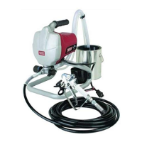
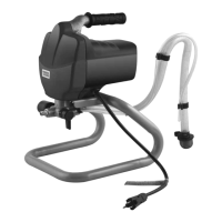
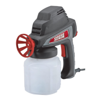
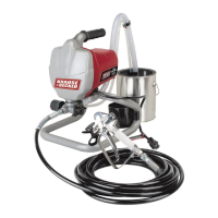
Labels and identifies the main components and controls of the airless paint sprayer.
Explains how the switch toggles between priming and spraying modes.
Describes the reversible and removable nozzle for cleaning and unclogging.
Details on adjusting the knob for different spray pressures, priming, or rolling.
Instructions for attaching the paint hose to the paint hose outlet and the paint gun.
Guidance on turning the Pressure Control Knob to the Low Pressure Spray setting.
Steps to turn off the power, switch to Prime mode, and relieve pressure.
Activating the trigger to relieve remaining pressure after switching to Prime mode.
Separating tubes, placing them in waste bucket, and submerging suction tube.
Setting switches, adjusting knob, powering on, and flushing storage fluids.
Reiterates the danger of paint injection and need for immediate medical attention.
Ensuring sprayer is primed, nozzle aligned, and practicing on scrap workpieces.
Guidance on adjusting pressure, keeping gun steady, avoiding fanning, and overlapping strokes.
Steps to clear a clogged spray gun tip by adjusting nozzle and spraying into a waste bucket.
Turning off power, switching to Prime, and draining paint from tubes before cleaning.
Submerging tubes in fluid, flushing until clear, and removing the spray tip.
Importance of cleaning all water or water-based materials to prevent corrosion before storage.
Steps include removing hose, disconnecting tubes, adding oil, and running sprayer briefly.
Troubleshooting for pump not priming, including clogged input valve and obstructed trigger.
Addressing decreased output, inconsistent flow, blobs, splatters, sags, and runs.
Solutions for bumpy texture, orange peel, blushing, uneven color, fish eyes, and contamination.
Improper disposal is hazardous; dispose of paint through local recycling facilities.
Manufacturer states repairs should be done by certified technicians, not the buyer.
Instructions to record the product's serial number or purchase date.
A detailed list of all parts with their corresponding numbers and quantities.
Indicates that an assembly diagram is provided for reference.
A visual representation showing the numbered parts of the sprayer in their assembled positions.
Details the 90-day warranty, exclusions, limitations, and rights.
Instructions on how to return the product for warranty service with proof of purchase.
| Brand | KRAUSE & BECKER |
|---|---|
| Model | 62915 |
| Category | Paint Sprayer |
| Language | English |