24
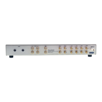
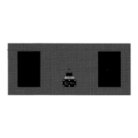
Back Panel Description
See Figure 6 and 7 on the previous pages
The amplifier back panel provides access to the input and output connections, 12 V trigger
inputs and outputs, and the AC power connection and switch. Back panel features and
their descriptions follow:
Outputs
3 Loudspeaker Binding Posts (one pair per channel)
Each channel has one positive and one negative binding post. They accept spade lugs
only.
Inputs
4 Single-ended Inputs (one per channel)
These are single-ended analog inputs with RCA connectors.
5 Balanced Inputs (one per channel)
These are balanced analog inputs with XLR connectors.
9 Input Switch
Set this switch for the style of connection being used, balanced/XLR or Single-
ended/RCA.
Remote Connections
6 12 VDC In/Out (12 V Trigger)
In,
The 12 V trigger allows you to turn the Evolution e Series amplifier on or to stand-
by from other components.
Out. The output sends 12 VDC (12 V trigger) power on/off signals to other Krell
components and other devices that incorporate a 12 V trigger, allowing whole systems
or parts of systems to be easily controlled remotely. Mono 3.5 mm connectors are used
in the following configuration: Tip = +12 V, Sleeve = GND.
Notes
When an Evolution e Series amplifier is in the operational mode, the 12 V trigger provides 12 Volts
of DC output. When the amplifier is in the stand-by mode or off, the DC output is 0 Volts. A
maximum of 30 mA is available from the 12 V trigger output.
Consult the owner's reference of the components used in a custom installation to take full
advantage of the remote capabilities of an Evolution e Series amplifier.
(SECTION THREE: Anatomy of an Evolution e Series Amplifier continued)