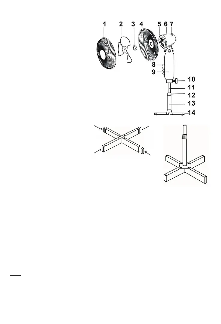
PARTS
1. Front guard
2. Fan blade
3. Guard nut and screw
4. Rear guard
5. Motor axis
6. Motor housing
7. Oscillaon control
8. Speed control switches
9. Switch box
10. Motor support xing screw
11. Upper tube
12. Fixing nut
13. Lower tube
14. Base
ASSEMBLING
• Fit the rubber ps at the feet end (if necessary).
• Cross the 2 feet to assemble them (see the drawing).
• Screw the base of the lower tube on the feet with 4 screws.
• Loosen and remove the telescopic screw and slide the cover screw on the base of the
lower tube unl it hides the fastening screws.
•Draw the upper tube from the lower tube and ghten the clamping ring aer seng
the desired height.
• Fix the motor unit of the fan on the top of the upper tube and ghten it with the locking
screw.
• Place the rear grid on the engine block and secure it with the central xing nut, turning
it clockwise.
• Posion the fan blade on the motor sha.
Note: Ensure that the notches connect to the end of the sha splines.
• Aach the blades with the central xing nut, turning counter clockwise.
• Aach the front grid to the top of the back grid and close the clips inwards.
• Fix the screw and lock nut through the hole in the boom of the grids.