GB-3
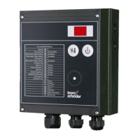
Part designations
2
5
6
3
1
7
8
9
4
10
10
1 LED display for program status and fault
messages
On/Off button
3 Reset/Information button
4 Connection for opto-adapter
5 BCU type label
6 Power module, replaceable
7 Power module type label
8 Parameter chip card, replaceable
9 Bus module, replaceable
10
M5 screw terminal for burner ground
Type designation (A), identification number (B), con-
struction stage(C), year/week of manufacture(D),
device number(E), device ID(F), voltage(G), fre-
quency(H), ambient temperature in Celsius(I)/Fahr-
enheit(J), enclosure(K)– see type label.
Elster GmbH
Osnabrück, Made in Germany
-
A
B
F
D EC
G
H
I
J
K
L
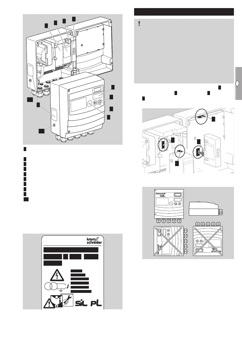
Installation
CAUTION
Please observe the following to ensure that the
BCU is not damaged:
– The device must not be installed in a public
place. It must be accessible to authorized
personnel only. Unauthorized personnel could
make changes which could cause the system
to become unsafe or dangerous.
– Dropping the device can cause permanent dam-
age. In this event, replace the entire device and
associated modules.
▷ The following components are sealed: 1 upper
housing section, power module, 3 bus module,
4 HMI. The BCU may only be installed and oper-
ated with undamaged seals.
1
4
2
3
▷ Installation position: vertical (cable glands point-
ing downwards) or down flat.
8888
8888
8888
▷
Distance between BCU and burner: recom-
mended <1m (3.3ft), max.5m (16.4ft).
▷
Affix the sticker (with the program step/fault
message description) in the required language
(available as an accessory).
 Loading...