- 1 -
Alle in dieser Betriebsanleitung
aufgeführten Tätigkeiten dürfen
nur von autorisiertem Fach per-
sonal ausgeführt werden!
WARNING! Incorrect installation,
adjustment, modification, operation
or maintenance may cause injury or
material damage.
Read the instructions before use.
This unit must be installed in accord-
ance with the regulations in force.
Toutes les actions mentionnées
dans les présentes instructions de
service doivent être exécutées par
des spécialistes formés et autori-
sés uniquement !
ATTENTION ! Un montage, un ré-
glage, une modi fication, une utilisa-
tion ou un entretien in adaptés ris-
quent d’engendrer des dom mages
matériels ou corporels.
Lire les instructions avant utilisation.
Cet appareil doit être installé en res-
pectant les règlements en vigueur.
Alle in deze bedrijfshandleiding
vermelde werkzaamheden mo-
gen alleen door technici worden
uitgevoerd!
WAARSCHUWING! Ondeskundi-
ge inbouw, instelling, wijziging,
bediening of onder houds werk zaam-
heden kunnen per soonlijk letsel of
materiële schade veroor zaken.
Aanwijzingen voor het gebruik lezen.
Dit apparaat moet overeenkom-
stig de geldende regels worden
geïnstalleerd.
Tutte le operazioni indicate nelle
presenti istruzioni d’uso devono
essere eseguite soltanto dal pre-
posto esperto autorizzato.
ATTENZIONE! Se montaggio,
re go lazione, modifica, utilizzo o
manu tenzione non vengono ese guiti
correttamente, possono veri ficarsi
infortuni o danni.
Si prega di leggere le istruzioni prima
di utilizzare il prodotto che dovrà ve-
nire installato in base alle normative
vigenti.
¡Todas las actividades indicadas
en estas Instrucciones de utiliza-
ción, sólo deben realizarse por
una persona formada y autorizada!
¡ADVERTENCIA! La instalación,
ajuste, modificación, manejo o man-
tenimiento incorrecto puede ocasio-
nar daños personales o mate riales.
Leer las instrucciones antes de usar.
Este dispositivo debe ser instalado
observando las normativas en
vigor.
TR CZ PL RUS H
DK S N P GR
➔
www.docuthek.com
WARNUNG! Unsachgemäßer
Ein bau, Einstellung, Verän de rung,
Be die nung oder War tung kann
Ver letzungen oder Sachschäden
verursachen.
Anleitung vor dem Gebrauch lesen.
Dieses Gerät muss nach den gelten-
den Vorschriften installiert werden.
All the work set out in these
operating instructions may only
be completed by authorized
trained personnel!
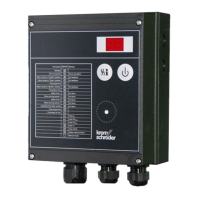
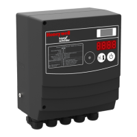
Brennersteuerung
BCU 370
Betriebsanleitung
Bitte lesen und aufbewahren
Zeichenerklärung
,
, , ... = Tätigkeit
= Hinweis
Inhaltsverzeichnis
Konformitäts erklärung 2
Prüfen 3
Einbauen 4
Leitungen auswählen 4
Verdrahten 6
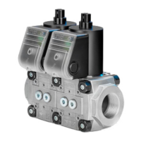
BCU 370 mit Stellantrieb
IC 20/IC 20..E 10
Einstellen 11
In Betrieb nehmen 12
Sicherheitsfunktionen prüfen 16
Handbetrieb 17
Hilfe bei Störungen 19
Flammensignal/
Parameter ablesen 27
Zubehör 29
Legende 30
Technische Daten 31
6.1.3.2 Edition 10.11
03250470 10.11 Fx/ivd
Burner control unit
BCU 370
Operating instructions
Please read and keep in a safe
place
Explanation of symbols
,
, , ... = Action
= Instruction
Commande de brûleur
BCU 370
Instructions de service
À lire attentivement et à
conserver
Légendes
,
, , ... = action
= remarque
Branderbesturing
BCU 370
Bedieningsvoorschrift
Lezen en goed bewaren a.u.b.
Legenda
,
, , ... = werkzaamheden
= aanwijzing
Unità di controllo
bruciatore BCU 370
Istruzioni d’uso
Si prega di leggere e conser-
vare
Spiegazione dei simboli
,
, , ... = Operazione
= Avvertenza
Control de quemador
BCU 370
Instrucciones de
utilización
Se ruega que las lean y conser-
ven
Explicación de símbolos
,
, , ... = Actividad
= Indicación
Contents
Declaration of conformity 2
Testing 3
Installation 4
Cable selection 4
Wiring 6
BCU 370 with actuator
IC 20/IC 20..E 10
Adjustment 11
Commissioning 12
Checking the safety functions 16
Manual mode 17
Assistance in the event
of malfunction 19
Reading off the flame signal
and the parameters 27
Accessories 29
Legend 30
Technical data 31
Sommaire
Déclaration de conformité 2
Vérifier 3
Montage 4
Choix des câbles 4
Câblage 6
BCU 370 avec servomoteur
IC20 / IC 20..E 10
Réglages 11
Mise en service 12
Vérifier les fonctions de
sécurité 16
Mode manuel 17
Aide en cas de défauts 19
Lire le signal de flamme
et les paramètres 27
Accessoires 29
Légende 30
Caractéristiques
techniques 31
Inhoudsopgave
Verklaring van
overeenstemming 2
Controleren 3
Inbouwen 4
Bedrading kiezen 4
Bedraden 6
BCU 370 met stelaandrijving
IC20/IC 20..E 10
Instellen 11
In bedrijf stellen 12
Veiligheidsfuncties
controleren 16
Handbedrijf 17
Hulp bij storingen 19
Aflezen van het vlamsignaal
en de parameters 27
Toebehoren 29
Legende 30
Technische gegevens 31
Indice
Dichiarazione di conformità 2
Verifica 3
Montaggio 4
Scelta dei conduttori 4
Cablaggio 6
BCU 370 con servomotore
IC20/IC 20..E 10
Regolazione 11
Messa in servizio 12
Controllo delle
funzioni di sicurezza 16
Funzionamento manuale 17
Interventi in caso di guasti 19
Lettura segnale di fiamma/
parametri 27
Accessori 29
Legenda 30
Dati tecnici 31
Índice
Declaración de conformidad 2
Comprobar 3
Montaje 4
Selección de los cables 4
Cableado 6
BCU 370 con servomotor
IC20 / IC 20..E 10
Ajuste 11
Puesta en funcionamiento 12
Comprobar las funciones
de seguridad 16
Funcionamiento manual 17
Ayuda en caso de averías 19
Lectura de la señal de
llama y de los parámetros 27
Accesorios 29
Leyenda 30
Datos técnicos 31