Do you have a question about the Krom Schroder BCU 560 and is the answer not in the manual?
Illustrates various burner configurations and applications.
Provides detailed wiring diagrams for various BCU models.
Details the procedure for checking gas valve and pipework tightness.
Details the GSD file required for PLC integration and data exchange.
Describes the sequence and parameters for burner start-up.
Explains safety-related parameter settings for protection.
Covers parameters related to air flow and actuator control.
Covers electrical wiring and connection requirements for the BCU.
Details the BCSoft software and required adapters.
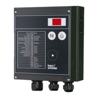
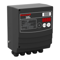
Explains the functionality, keys, and modes of the OCU.
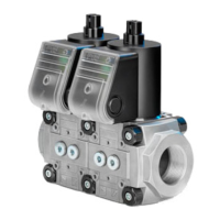
Covers the electrical connection requirements for the BCM 500.
Details safety integrity levels, diagnostic coverage, and failure probabilities.
Explains the safety shut-down procedure and its causes.
Details the fault lock-out procedure and reset requirements.
| Type | Burner Control Unit |
|---|---|
| Model | BCU 560 |
| Frequency | 50/60 Hz |
| Input Voltage | 24 V DC |
| Number of Digital Inputs | 8 |
| Number of Digital Outputs | 6 |
| Manufacturer | Krom Schroder |
| Approvals | CE |
| Operating Temperature | -20 to +60 °C |
| Storage Temperature | -20°C to +70°C |
| Relative Humidity | 95% (non-condensing) |
| Communication Interface | Modbus RTU |