GB-3
▷ The switching differential of the pressure switch
may not exceed ±10% of the set value.
Example:
inlet pressure p
u
= 100mbar,
set switching pressure p
u
/2 = 50mbar,
max. switching differential 50mbarx 10%=
5mbar.
The switch-on and switch-off pressure must be
between 45mbar and 55mbar.
Wiring
CAUTION
Electric shocks can be fatal!
– Before working on possible live components,
ensure the unit is disconnected from the power
supply.
Please observe the following to ensure that the TC
is not damaged during installation:
– Incorrect wiring may result in unsafe states and
the destruction of the tightness control, the au-
tomatic burner control unit or the valves.
– Do not reverse L1(+) and N(–).
Disconnect the system from the electrical power
supply.
Shut off the gas supply.
Open the housing cover of the TC.
▷ Electrical connection: 2.5mm
2
terminals.
▷
The data on the type label must comply with the
mains voltage.
4 Prepare knock-out holes at the appropriate cable
glands.
▷ Use the NO contacts 3COM and 2NO on the
pressure switch (p
e
/2=p
u
/2).
5 Electrically wire TC410.
1 2 3 4 5 6 7 8910 11 12 13
max. 1 A,
264 V
L1(+)
V1
L1(+)
V2
OK
ϑ
V2
V1
L1(+)
N(-)
ϑ
max
p
e
/2
N
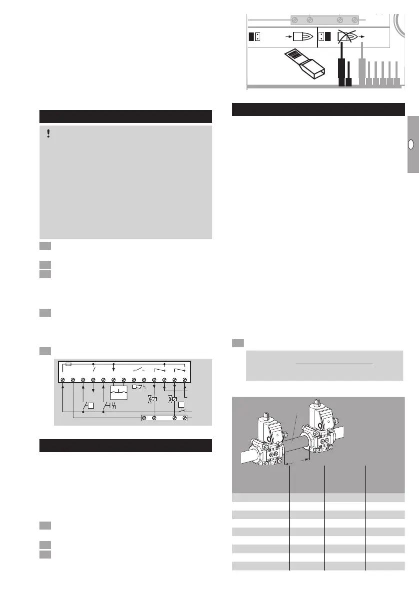
Setting the test instant
▷
The test instant (MODE) can be set inside the
housing using a jumper.
▷ Mode 1: test before burner start-up with incom-
ing ϑsignal (factory setting).
▷
Mode 2: test after burner run with outgoing ϑsig-
nal and also after switching on the mains voltage.
▷ Without jumper = test before burner start-up.
Disconnect the unit from the electrical power
supply.
Unscrew the housing cover.
Set the test instant with a jumper, MODE 1 or2.
N
12 12
"TEST:"
TEST"
:"
Setting the test periodt
P
▷
The test period t
P
is set at the works to 10s
(100s) on TC410-1 (TC410-10) and can be
changed with a jumper in increments of 10s
(100s) to a max. of 60s (600s).
▷ Without jumper = 60s (600s).
▷
The longer the test periodt
P
, the smaller the leak-
age rate at which a safety shut-down is triggered.
▷ If no leakage rate is specified, we recommend
the max. test period is set.
▷
If a leakage rate is specified, find the test pe
-
riodt
P
from the following:
Q
max.
= max. flow rate [m
3
/h]
Q
L
= Q
max.
[m
3
/h] x 0.1% = leakage rate [l/h]
p
u
= inlet pressure [mbar]
V
P
= test volume [l], see page3 (Values for
valve and pipe volume)
▷
The tightness control TC requires a minimum
start rate in order to carry out tightness tests
on slow opening valves:
up to 5l (1.3gal) test volume V
P
= 5% of maxi-
mum flow rateQ
max.
,
up to 12l (3.12gal) test volume V
P
= 10% of
maximum flow rateQ
max.
.
Determine test period t
P
.
t
P
[s] = 4x
(
p
u
[mbar] x V
P
[l]
+ 1 s
)
Q
L
[l/h]
Values for valve and pipe volume
P
V1
V2
Valves
Valve
volume
V
V
[l]
Nominal
size
DN
Pipe
volume
V
R
[l/m]
VG 10 0.01 10 0.1
VG 15 0.07 15 0.2
VG 20 0.12 20 0.3
VG 25 0.2 25 0.5
VG 40/VK 40 0.7 40 1.3
VG 50/VK 50 1.2 50 2
VG 65/VK 65 2 65 3.3
VG 80/VK 80 4 80 5
VG 100/VK 100 8.3 100 7.9
 Loading...