GB-4
Valves
Valve
volume
V
V
[l]
Nominal
size
DN
Pipe
volume
V
R
[l/m]
VK 125 13.6 125 12.3
VK 150 20 150 17.7
VK 200 42 200 31.4
VK 250 66 250 49
VAS 1 0.08
VAS 2 0.32
VAS 3 0.68
VAS 6 1.37
VAS 7 2.04
VAS 8 3.34
VAS 9 5.41
VCS 1 0.05
VCS 2 0.18
VCS 3 0.39
VCS 6 1.11
VCS 7 1.40
VCS 8 2.82
VCS 9 4.34
Calculation example:
Q
max.
= 100 m
3
/h
p
u
= 100 mbar
V
P
= V
V
+ L x V
R
= 7 l
Q
L
= 100 m
3
/h x 0.1% = 100 l/h
4 x
(
100 x 7
+ 1 s
)
= 32 s
100
Set the next highest value (in this example 40s)
with the jumper.
Disconnect the unit from the electrical power
supply.
Unscrew the housing cover.
4 Connect the jumper to the pin for the required
test periodt
P
between 10 and 60 s (100 and
600 s).
12 12
"TEST:"
TEST"
:"
5 Position the housing cover and screw tight.
6 Mark the set test periodt
P
on the type label with
a waterproof pen.
tp(s) 10 20 30 40 50 60
D-49018 Osnabrück, Germany
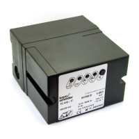
Commissioning
▷ Indicators and operating controls:
TEST
OK
1
2
= TEST phase (yellow)
= operating signal (green)
= fault valve 1 (red)
= fault valve 2 (red)
= reset button
Main switch on.
Apply mains voltage to terminal1.
▷
If one or both fault lamps (red) are lit, wait ap-
prox. 5s then press the reset button. The fault
signal goes out.
Start the tightness test.
▷ Mode , test before burner start-up.
4 Voltage at terminal3.
Or
▷ Mode , test after burner run.
5 Mains voltage at terminal1 and renewed test
after switching off the voltage to terminal3.
The test begins:
▷ LED
is lit.
After test, if the valves are tight:
▷ LED
is lit.
MODE 1: voltage at terminal 4.
Or
MODE 2: voltage at terminal 4 does not arrive
until voltage is applied to terminal3.
After test, if the valves are leaking: voltage at termi-
nals 8 and9.
▷ LED
is lit.
Or
▷ LED
is lit.
Power failure
▷ If the power fails briefly during the test or during
operation, the tightness test will restart auto-
matically.
▷
After a power failure during a fault, both red fault
lamps will be lit.
Assistance in the event of
malfunction
CAUTION
Electric shocks can be fatal!
–
Before working on possible live components, en-
sure the unit is disconnected from the power supply.
– Fault-clearance must only be undertaken by
authorized trained personnel.
– (Remote) resets may only be conducted by
authorized personnel.
▷ Faults may be cleared only using the measures
described below.
 Loading...