Do you have a question about the Krone KS2900 and is the answer not in the manual?
General description of the KS2900 digital pressure manometer and its connector type.
Warnings about excessive pressure, foreign matter, and improper handling to prevent damage.
Guidelines for manual handling, safe operation by trained personnel, and environmental considerations.
Provides detailed dimensional drawings and specifies the 8-pin connector (B8B-XH-A).
Details model, sensor type, pressure range, display accuracy, temperature drift, and power supply.
Covers setting methods, hysteresis, comparator outputs, and analog output specifications.
Details output display type, display rate, and overflow indication.
Details operating temperature, humidity, altitude, pollution degree, and protection standards.
Covers material, dimensions, mounting, insulation resistance, and withstand voltage.
Detailed explanation of the function for each pin in the 8-pin B8B-XH-A connector.
Illustrates wiring configurations for NPN and PNP transistor output options.
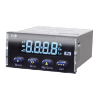
Identifies the components of the 7-segment LCD display and associated indicators.
Explains the basic functions of the MODE, SHIFT, UP/ZERO, and SET keys.
Illustrates the sequence for entering and navigating setting modes.
Configuration of Hi/Lo alarm points, conditions, and logic modes.
Adjusting hysteresis for outputs and setting delay times for transitions.
Setting alarm activity status and backlight blinking behavior.
Commands for operation modes, zero setting, sampling, display rate, and analog output.
Commands for accessing modes, backlight control, averaging, and serial communication.
Detailed table showing parameter settings and their default/selectable values for Mode 1.
Specific settings for comparison logic, hysteresis, delay, sampling, and output modes.
Details settings for backlight continuance, moving average cycle, and serial output in Mode 2.
Details the one-year warranty against defects in materials and workmanship.
Lists conditions and actions, such as improper installation, that void the product warranty.
Notes on suggestions, buyer responsibility for fitness, and KRONE's limited liability.
| Brand | Krone |
|---|---|
| Model | KS2900 |
| Category | Measuring Instruments |
| Language | English |