Pinnumber Terminalname Functioncontents
12345678
Pin1
Pin2
Pin3
Pin4
Pin5
Pin6
Pin7
Pin8
Hi
Go(Good)
Lo
GND(COM)
ACOM(-)
AOUT(+)
GND(COM)
V(+)
HiAlarmoutput
NPNopencorrectoroutput
PNPtransistoroutput(option)
Gosignaloutput
NPNopencorrectoroutput
PNPtransistoroutput(option)
LoAlarmoutput
NPNopencorrectoroutput
PNPtransistoroutput(option)
Power(common=GND)
Analogoutput(common)
Analogoutput(out)
Power(common=GND)
Powersupply(DC12/24V)
Port(+)
Port(−)
JST
:B8B-XH-A(8pins)
5.Terminal description
5-1B8B-XH-A(8pinsconnector)
-5-
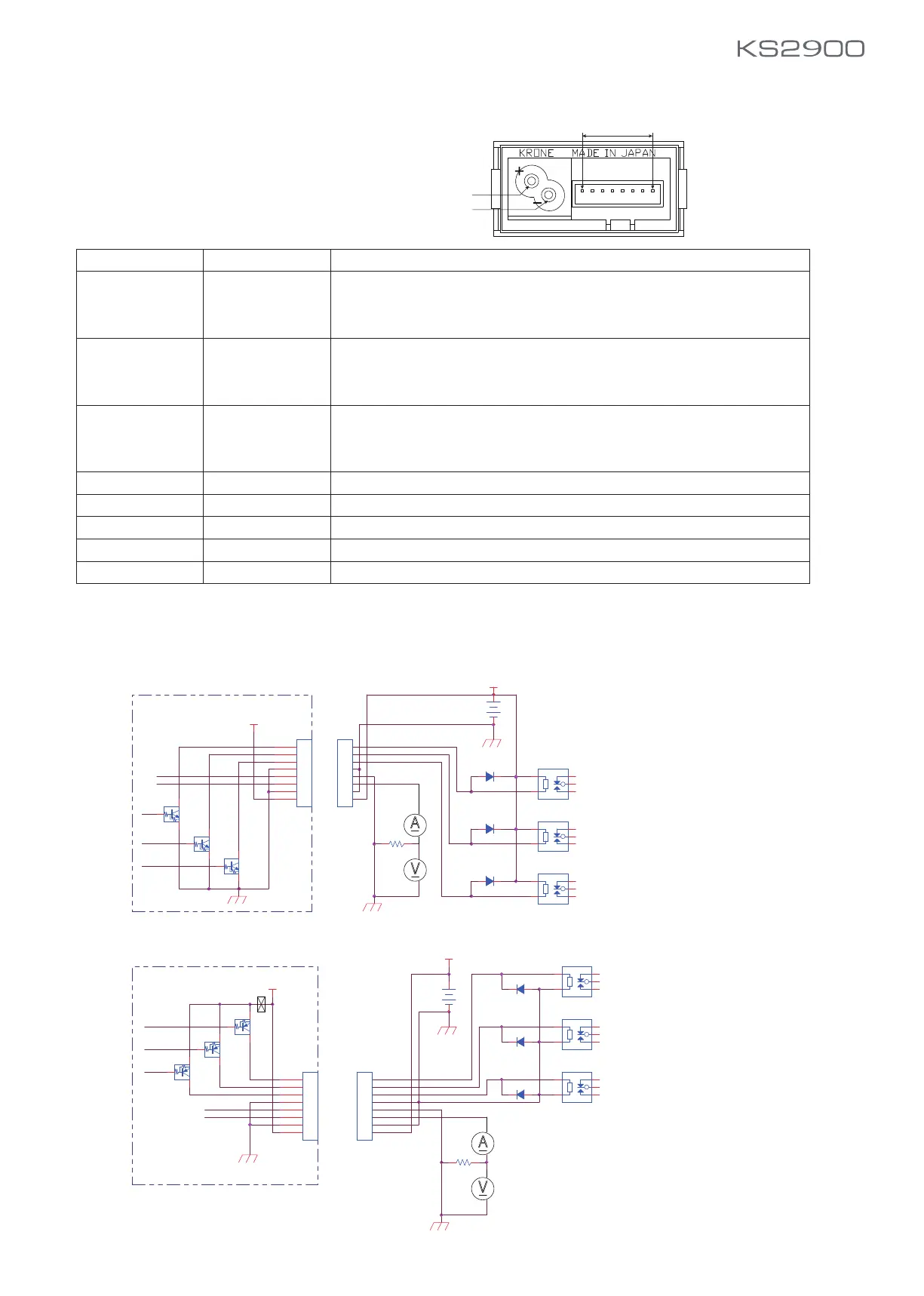
6. Application
6-1B8B-XH-A(8pinsconnector)
ApplicationSchematic/NPNopencorrectoroutput
ApplicationSchematic/PNPtransistoroutput(option)
*AnalogoutputRecommendationTerminationresistance
4-20mA:250Ω(max.:350Ω)
1-5V:10kΩ(min.:1kΩ)
*P1:connectorcable=Option
Vcc
Vcc
Hi
Go
Lo
com
AO-
AO+
GND
12/24VDC
4-20mAout
Lo
Hi
Go
V
Fuse/1A
A
DC12/24V
Hi
Go
Lo
250
B
EC
Relay-Hi2
3
2 4
5
1
B
EC
B8B-XH-A
1
2
3
4
5
6
7
8
1
2
3
4
5
6
7
8
Diode
Diode
Diode
Relay-Lo1
3
2 4
5
1
Relay-Go2
3
2 4
5
1
B
EC
−
+
Vcc
Vcc
V
DC12/24V
4-20mAout
Hi
Go
Lo
Lo
Hi
Go
A
Hi
Go
Lo
com
AO-
−
+
AO+
GND
12/24
VDC
B8B-XH-A
1
2
3
4
5
6
7
8
1
2
3
4
5
6
7
8
2
1 3
Relay-Lo2
3
2 4
5
1
2
1 3
2
1 3
Relay-Go1
3
2 4
5
1
Relay-Hi1
3
2 4
5
1
250
Diod6
Diod8
Diod5
P1
P1
 Loading...