41
Fan Powered Terminal Units IOM
PNEUMATIC CONTROLS
GENERAL
SINGLE FUNCTION PNEUMATIC CONTROLLER CONTROL
SEQUENCES (1300-1305, 1400-1401)
To properly balance the system, all ductwork and outlets
must be installed and connected tightly. Reference piping/
wiring diagram on unit for specics for the control sequence
selected for the unit.
UNITS WITH SINGLE-FUNCTION CONTROLLERS
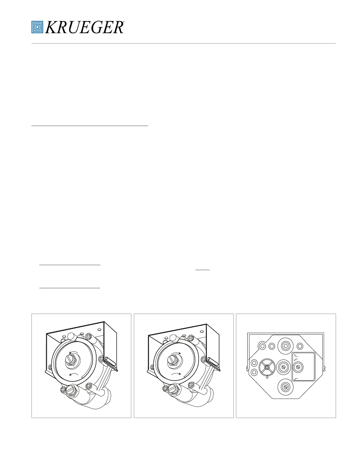
1. Determine sequence of operations; Reverse-Acting,
Normally Closed [RANC], Direct-Acting, Normally Open
[DANO]. This can be accomplished by reading the diagram
axed to the unit. The standard RANC controller is gray
colored; the DANO controller is beige. See Figures 10-12.
2. Check that main air pressure at the controller. Main air
should equal 18 to 25 psi. Main air must be clean and dry.
3. Check for primary airow in the inlet duct, using a
dierential pressure sensor tapped into the dierential
pressure sensor line tees.
4. Verify that the installed room thermostat is compatible
with the unit control.
5. Close the primary air damper.
a. RANC— disconnecting the actuator from the controller
should allow the damper to close completely.
b. DANO — connecting to 20-psi air supply directly to the
actuator should close the damper completely.
6. Start the blower motor by doing one of the following:
KLPS, KQFS & QFC Units:
Both RANC and DANO — Connect electrical power to the
blower motor control.
KLPP, KQFP & QFV Units:
RANC— Connect the main compressed air line to the
blower control, bypassing the thermostat input.
DANO — Disconnect the thermostat line from the blower
controls. These steps should energize the fan.
7. Balance the supply outlets using a proportional air
volume method.
a. With the blower discharging full volume (SCR on max
setting), measure the total air volume.
b. Calculate the percentage of the design air volume
needed by each outlet.
c. Multiply the total air volume by the percent-of-design
air volume for each diuser.
d. Balance each outlet according to the requirements
calculated above.
8. Balance the unit fan discharge:
a. Measure the total ow discharging from the unit.
b. Adjust the discharge ow from the unit using the unit
electronic speed control (SCR).
9. Reconnect the damper actuator and/or the thermostat
tubing to the velocity controller with the fan still running.
Make sure the piping is as shown on the unit piping/
wiring diagram.
10. Balance the primary (cooling) air volume:
NOTE: To balance the primary air side of the KLPP,
KQFP & QFV unit only, the blower motor must be
disconnected.
a. Connect the Magnehelic or inclined manometer (0 to
2.0 in. wg scale, maximum) to the dierential pressure
sensor tubing.
b. Measure the volume of air owing through the inlet
using the calibration curve axed to the unit.
RANC
1. With a 0 psi thermostat signal, measure the unit
maximum airow.
2. Rotate the “HI” adjustment knob on the velocity
controller, adjust airow to the desired maximum
setting.
LO
HI
CSC-2000
Q.A.
DMPR.NO.
I
N
C
R
E
A
S
E
I
N
C
R
E
A
S
E
LO
HI
CSC-2000
Q.A.
DMPR.NO.
I
N
C
R
E
A
S
E
I
N
C
R
E
A
S
E
DAMPER
RESET START
LO STAT AP
RESET SPAN
HI STAT AP
G
M
B
H
L
T
NO
NC
I
N
C
H
I
N
C
H
FIGURE 10 – Pneumatic Single Function
Volume Controller (Normally Open) for
Pneumatic Control Unit (Beige Color)
FIGURE 11 – Pneumatic Single Function
Volume Controller (Normally Closed) for
Pneumatic Control Unit (Grey Color)
FIGURE 12 – Multi-Function Reset Volume
Controller