Home
Kubota
Tractor
G1800 2WS
Kubota G1800 2WS User Manual
5
of 1
of 1 rating
392 pages
Give review
Manual
Specs
To Next Page
To Next Page
To Previous Page
To Previous Page
Loading...
S.1
ENGINE
G1700'G1800'G1900'G2000
WSM,10835
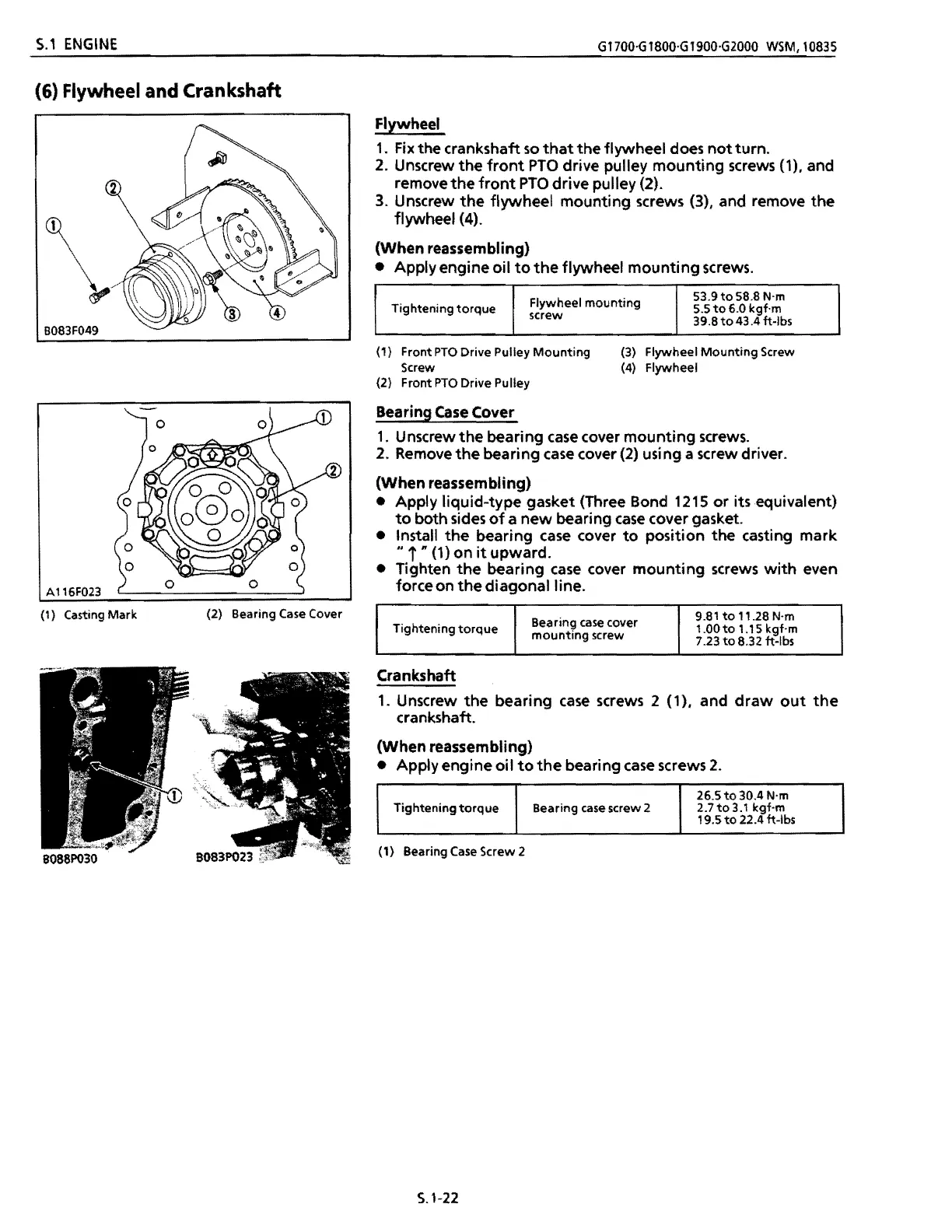
(6)
Flywheel
and
Crankshaft
~
\
B083F049
A116F023
(1)
Casting
Mark
(2)
Bearing
Case
Cover
Flywheel
1.
Fix
the
crankshaft
so
that
the
flywheel
does
not
turn.
2.
Unscrew
the
front
PTO
drive
pulley
mounting
screws
(1),
and
remove
the
front
PTO
drive
pulley
(2).
3.
Unscrew
the
flywheel
mounting
screws
(3),
and
remove
the
flywheel
(4).
(When
reassembling)
•
Apply
engine
oil
to
the
flywheel
mounting
screws.
Flywheel
mounting
53.9
to
58.8
N'm
Tightening
torque
55
to
6.0
kgf·m
screw
39.8
to
43.4
ft-Ibs
(1)
Front
PTO
Drive
Pulley
Mounting
(3)
Flywheel
Mounting
Screw
Screw
(4)
Flywheel
(2)
Front
PTO
Drive
Pulley
Bearing
Case
Cover
1.
Unscrew
the
bearing
case
cover
mounting
screws.
2.
Remove
the
bearing
case
cover
(2)
usi
ng
a
screw
driver.
(When
reassembling)
•
Apply
liquid-type
gasket
(Three
Bond
1215
or
its
equivalent)
to
both
sides
of
a
new
bearing
case
cover
gasket.
•
Install
the
bearing
case
cover
to
position
the
casting
mark
..
i
n
(1)
on
it
upward.
•
Tighten
the
bearing
case
cover
mounting
screws
with
even
force
on
the
diagonal
line.
Bearing
case
cover
9.81
to
11.28
N'm
Tightening
torque
1.00
to
1.1
5
kgf·m
mounting
screw
7.23
to
8.32
ft-Ibs
Crankshaft
1.
Unscrew
the
bearing
case
screws
2
(1),
and
draw
out
the
crankshaft.
(When
reassembling)
•
Apply
engine
oil
to
the
bearing
case
screws
2.
Tightening
torque
Bearing
case
screw
2
265
to
30.4
N'm
2.7to3.1
kgf·m
19.5
to
22.4
ft-Ibs
(1)
Bearing
Case
Screw
2
5.1-22
168
167
169
Table of Contents
Section 1
123
Table of Contents
123
General Safety
125
General Precaution
125
LUBRICANTS. Fuel and COOLING WATER
126
Tightening Torques (General Use Screws. Bolts Andnuts)
127
Maintenance Check List
128
Check and Maintenance
129
Check Points of Daily or each Use
129
Check Points of Initial 50 Hours
131
Check Points of Every 50 Hours
132
Check Points of Every 100 Hours
133
Check Points of Every 200 Hours
135
Check Points of Initial 200 Hours
135
Check Points of Every 800 Hours
137
Check Points of Every 2 Years
139
Special Tools
140
Section 2
145
Troubleshooting
147
Servicing Specifications
149
Tightening Torques
155
Checking, Disassembling and Servicing
156
Disassembling and Assembling
156
Separating Engine
156
Checking and Adjusting
159
ENGINE Body
159
Disassembling and Assembling
160
External Components
160
Cylinder Head and Valves
161
Injection Pump and Speed Control Plate
163
Timing Gears, Camshaft and Fuel Camshaft
164
Flywheel and Crankshaft
168
Cylinder Head and Valves
170
Servicing
170
Piston and Connecting Rod
173
Timing Gear and Camshaft
175
Crankshaft
177
Cylinder
182
Checking
183
DISASSEMBLING and Assembllng
183
Lubricating System
183
Servicing
183
Checking and Adjusting
184
COOLING System
184
Fan Belt
184
Radiator
185
Thermostat
185
Disassembling and Assembling
186
Thermostat and Water Pump
186
Checking and Adjusting
187
FUEL System
187
Injection Nozzle
187
Injection Pump
188
DISASSEMBLING and Assembllng
190
Injection Nozzle
190
Section 3
191
Troubleshooting
193
Servicing Specifications
195
Tightening Torques
201
Checking, Disassembling and Servicing
202
Disassembling and Assembling
202
Separating Engine
202
Checking and Adjusting
205
ENGINE Body
205
Disassembling and Assembling
206
Cylinder Head and Valves
207
Servicing
216
Cylinder
228
Checking
229
DISASSEMBLING and Assembllng
229
LUBRICATING System
229
Servicing
229
Checking and Adjusting
230
COOLING System
230
Fan Belt
230
Radiator
231
Thermostat
231
Thermostat and Water Pump
232
Carburetor
233
Checking and Adjusting
233
FUEL System
233
Checking and Adjsuting
234
IGNITION System
234
Ignition Coil
235
Distributor
236
Section 4
237
Troubleshooting
239
Servicing Specifications
240
Tightening Torques
241
Checking. Disassembling and Servicing
242
Disassembling and Assembling
242
SEPARATING TRANSMISSION and REAR Axle
242
Checking and Adjusting
244
HYDROSTATIC Transmission
244
Disassembling and Assembling
246
Separating Hydrostatic Transmission
246
Disassembling Hydrostatic Transmission
248
Assembling Hydrostatic Transmission
252
Disassembling and Assembling
258
Transmission Case
258
Transmission Case and Rear Axle Case
258
Rear Axle Case
260
Servicing
263
Transmission Case and Rear Axle Case
263
Section 5
265
Servicing Specifications
267
Tightening Torques
267
Troubleshooting
267
Checking and Adjusting
268
Checking, Disassembling and Servicing
268
Disassembling and Assembling
270
Servicing
271
Section 6
273
Servicing Specifications
275
Tightening Torques
275
Troubleshooting
275
Checking, Disassembling and Servicing
276
Disassembling and Assembling
276
Front Wheel and Checking and Adjusting
276
Checking and Adjusting
277
Disassembling and Assembling
278
Servicing
280
Section 7
281
Servicing Specifications
283
Tightening Torques
283
Troubleshooting
283
Checking and Adjusting
284
Checking, Disassembling and Servicing
284
Disassembling and Assembling
286
Section 8
289
Servicing Specifications
291
Tightening Torques
291
Troubleshooting
291
Checking and Adjusting
292
Checking, Disassembling and Servicing
292
Control Valve
292
Disassembling and Assembling
293
Checking and Adjusting
294
Control Valve Adaptor
294
Disassembling and Assembling
295
Lift Cylinder
295
Section 9
297
Servicing Specifications
299
Troubleshooting
299
Checking and Adjusting
300
Checking, Disassembling and Servicing
300
Disassembling and Assembling
302
Servicing
304
Section 10
307
Troubleshooting
309
Servicing Specifications
312
Checking
314
Checking, Disassembling and Servicing
314
Checking
315
Main Switch
315
Starting System
315
Glow Plug [G1700·G1800·G1900
317
Starter
317
Disassembling and Assembling
318
Starter [G1700·G1800·G1900
318
Starter [G2000
319
Starter [G1700'G1800'G1900] : Reduction Type
320
Servicing
322
Starter [G1700·G1800.G1900]
322
Starter [G2000
325
Starter [G1700-G1800'G1900] : Reduction Type
327
AC Dynamo Type [G1700·Gl800·G1900·G2000
331
Charging System
331
Checking
331
Alternator Type [G1700·G1900
332
Disassembling and Assembling
332
Alternator Type [G1700'G1900
335
Servicing
335
Checking
337
Electrical Equipment
337
Oil Pressure Switch
337
Coolant Temperature Sensor
338
Fuel Pump
338
Fuel Level Sensor
339
Brake Switch
340
Engine Stop Solenoid [G1700·G1800·G1900]
340
Fuel Cut off Solenoid [G2000
340
Head Light Switch
340
Combination Box [G1700-G1800'G1900
341
PTO Switch
341
Seat Switch
341
Relay Box [G2000
342
Coolant Temperature Switch
343
Relay
343
Section 11
351
General Precautions
353
Mower Identification
353
Lubricants
354
Tightening Torques (General Use Screws, Bolts and Nuts
354
Check and Maintenance
355
Check Points of Daily or each Use
355
Maintenance Check List
355
Check Point of Initial 50 Hours
359
Check Point of Every 150 Hours
360
Check Point of Every 50 Hours
360
Check Point of Every 2 Years
361
S-L
365
Servicing Specifications
365
Troubleshooting
365
Tightening Torques
367
Dismounting Mower
368
Mounting and Dismounting
368
Checking and Adjusting
375
Checking, Disassembling and Servicing
375
Disassembling and Assembling
379
Side Discharge Mower
379
Rear Discharge Mower
384
Servicing
391
5
Based on 1 rating
Ask a question
Give review
Questions and Answers:
Need help?
Do you have a question about the Kubota G1800 2WS and is the answer not in the manual?
Ask a question
Kubota G1800 2WS Specifications
General
Engine Type
Diesel
Engine Power
18 hp
Cylinders
3
Fuel Type
Diesel
Transmission Type
Hydrostatic
Drive Type
2WD
Tire Size (Rear)
23x10.50-12
Related product manuals
Kubota G1900 2WS
392 pages
Kubota G1700 4WS
392 pages
Kubota G1900 4WS
392 pages
Kubota G2160
395 pages
Kubota G2460G
395 pages
Kubota GR1600EC2
241 pages
Kubota G2000 4WS
392 pages
Kubota GCD 600 BX
16 pages
Kubota G2160-R48S
395 pages
Kubota G21LD / G21HD
328 pages
Kubota M6040
559 pages
Kubota WSM L4060
801 pages

 Loading...