164
ENGLISH
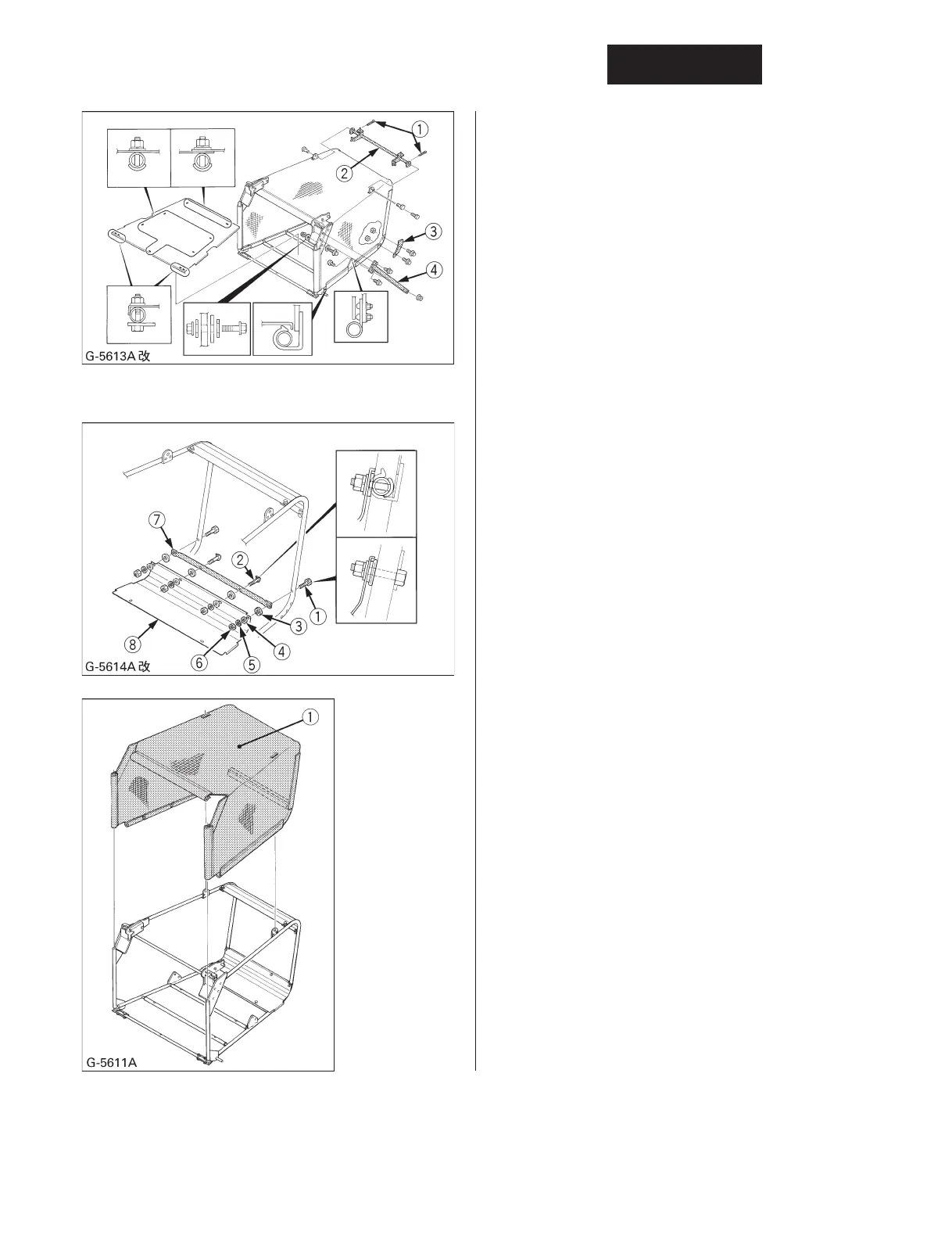
3. Remove 2 clevis pins, 2 cotter pins, 2 flange bolts
and the height adjust stay from the top of
container frame.
4. Remove 4-1/4 hex bolts, 7-1/4 curved bolts and
bottom plate from container frame.
5. Remove 4-M6 bolts and 2 side beams from
container.
6. Remove 4-M6 bolts and 2 bottom corner plates
from container frame.
(1) Cotter-pin
(2) Height adjust stay
(3) Bottom corner plate
(4) Side beam
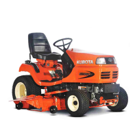
7. Remove 2 curved bolts, 2 hex bolts, 4 spacers, 4
plain washers,4 lock washers, 4 hex nuts, bottom
corner plate and pipe frame bag from bag frame.
(1) Curved bolt
(2) Hex bolt
(3) Spacer
(4) Plain washer
(5) Lock washer
(6) Hex nut
(7) Pipe frame bag
(8) Bottom corner plate
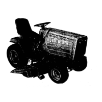
8. Then remove the container net from frame.
9. To attach new or cleaned net, reverse the above
procedures and be sure to install removed
components.
(1) New or cleaned net