60
ENGLISH
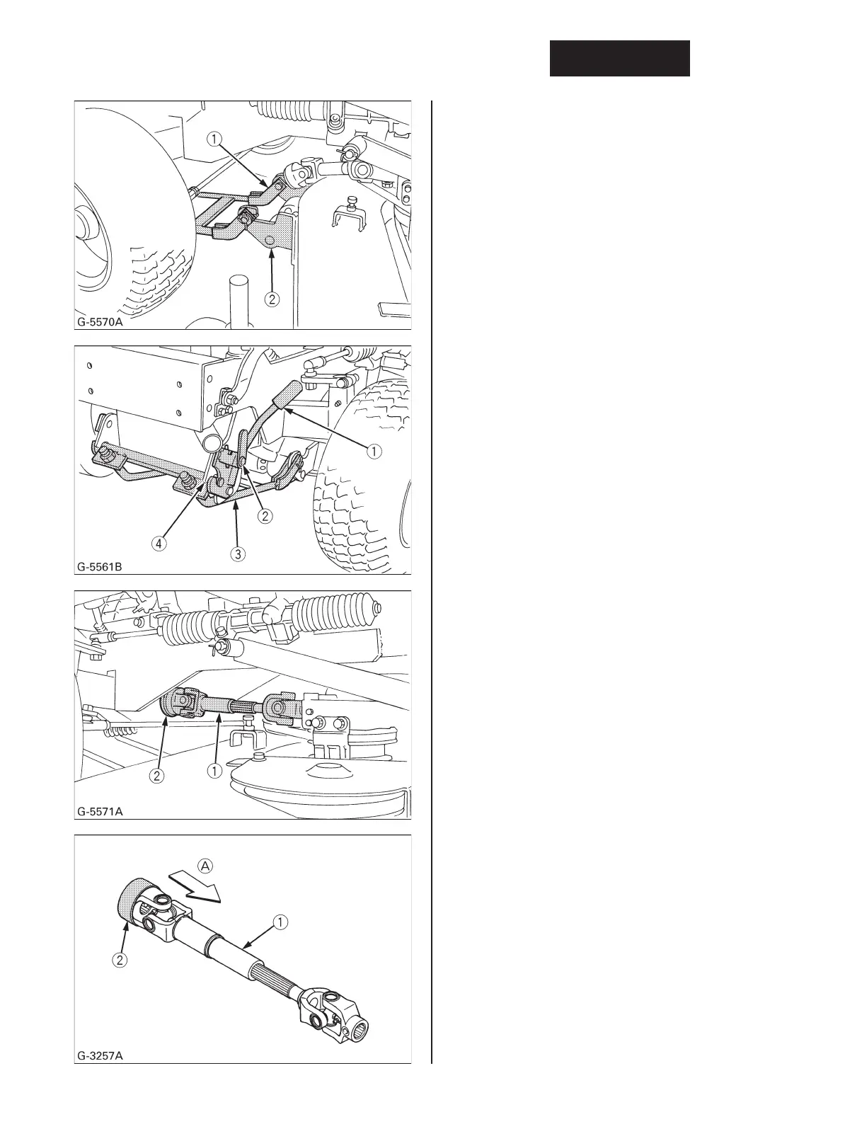
7. Attach the front links to the front roller brackets.
(1) Front link
(2) Front roller bracket
NOTE:
¡ Adjust the length L of the front link.
(See “Adjusting The Parallel Linkage” section)
8. Pull the lever fulcrum fixing pin and turn it counter
clockwise to lock.
9. Hook and raise the front link with the link fixing
lever, then lay the link fixing lever onto the front
bracket of the machine.
(1) Link fixing lever
(2) Lever fulcrum fixing pin
(3) Front link
(4) Front bracket
10. Turn the lever fulcrum fixing pin clockwise and
push it into position to fix the link fixing lever.
11. Pull back the coupler of the universal joint.
Push the universal joint into the PTO shaft until
the coupler locks.
Slide the universal joint back and forth to make
sure the universal joint is locked securely.
IMPORTANT:
¡ Finally pull the universal joint to check if it is tight
in position.
(1) Universal joint (A) “PULL”
(2) Coupler
NOTE:
¡ For dismounting the mower deck, reverse the
above procedures.