2-S21
GL6000, GL7000, GL9000, GL11000, WSM
GENERATOR
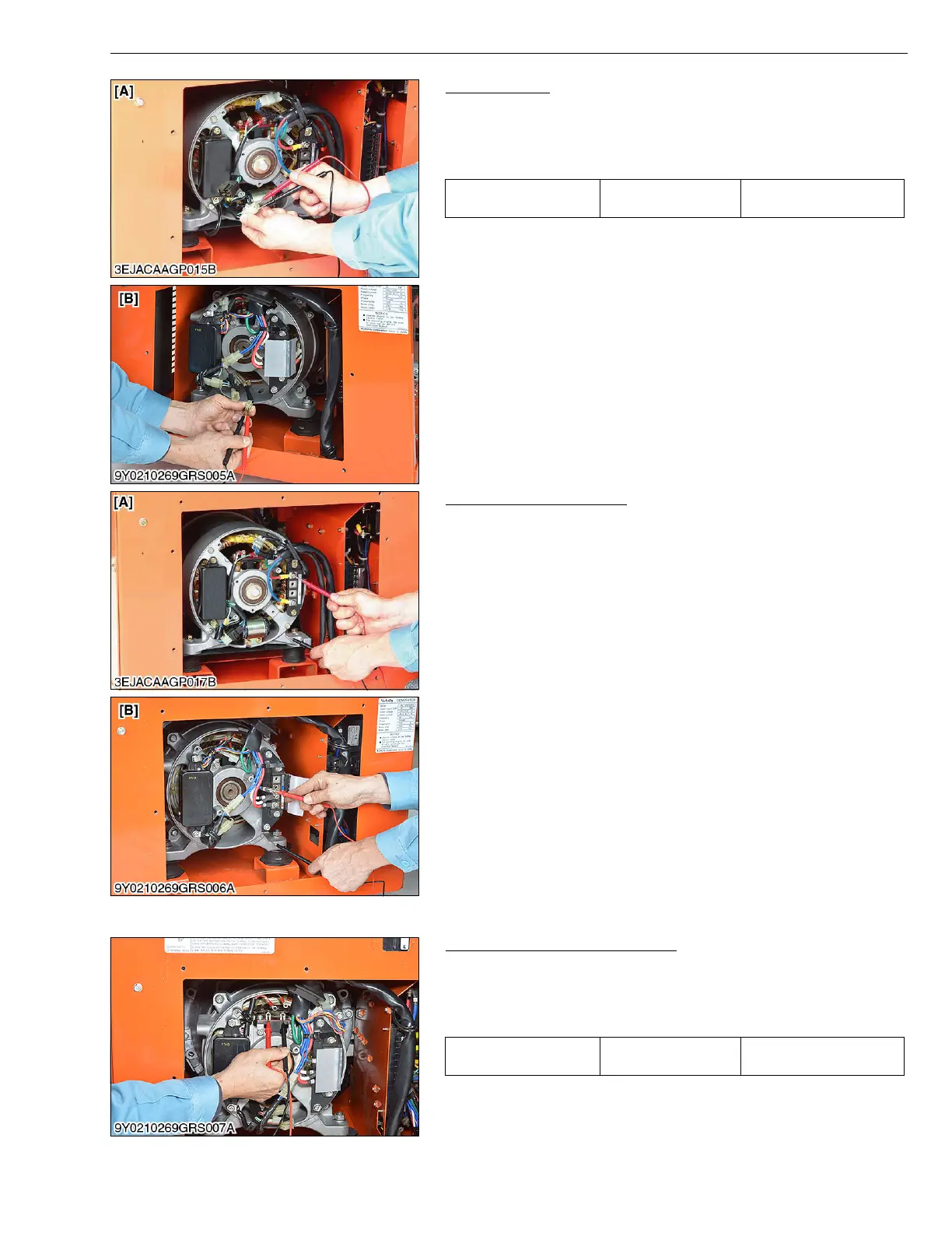
Detecting Coil
1. Measure the coil resistance between each auxiliary winding.
2. If the factory specification is not indicated, replace the stator or
contact service station.
(Refer to "5. WIRING DIAGRAM” (2-M8).)
W1068968
Grounding of Stator Coil
1. Measure the insulation resistance between each stator winding
and lamination with a megohm meter.
2. Reading should be more than 1 M at 500 V.
3. If continuous, replace the stator or contact service station.
W1069388
(3) Rotor Coil
Main Field Winding (Rotor Coil)
1. Measure the coil resistance between each end of field coil.
2. If the resistance is not as specified, replace the rotor assembly or
contact service station.
(Refer to "5. WIRING DIAGRAM” (2-M8).)
W1026895
Resistance Factory spec.
Refer to "2. SERVICING
SPECIFICATION” (2-S6).
[A] G6000, GL7000 [B] GL9000, GL11000
[A] G6000, GL7000 [B] GL9000, GL11000
Resistance Factory spec.
Refer to "2. SERVICING
SPECIFICATION” (2-S6).
 Loading...