PAGE
2
NOTE:
The OEM passing lamps draw up to 4.6 amps when they are on.
NOTE: Make sure the key fob is with you on ’07 and later models,
or the siren (if equipped) has been disarmed with the key
fob on ‘06 and earlier models.
To prevent the bike from accidentally starting,
remove the main fuse before starting this
procedure.
STEP 2
If your motorcycle is equipped with a main fuse, remove it as
outlined in the service manual.
Avoid potential electrical shock! Disconnect the
battery before starting this procedure.
STEP 3 If your motorcycle is equipped with a main circuit breaker,
remove the seat and disconnect the negative terminal from
the battery.
STEP 4 Remove the outer fairing as outlined in the service manual.
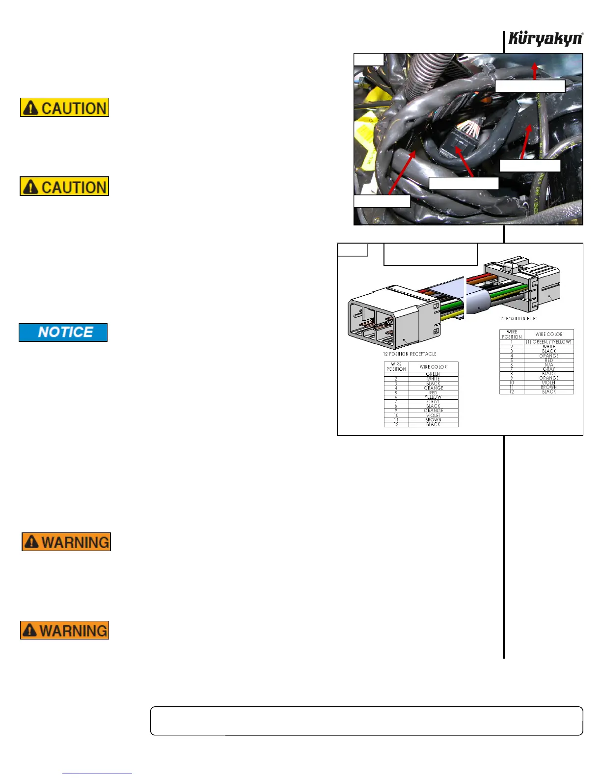
STEP 5 Disconnect the 12 pin fairing cap connector located on the
inside of the right (sitting on bike) side inner fairing support
bracket. PIC 1 You may have to move some of the wire
harnesses under the radio to locate the correct connector.
Küryakyn recommends the use of dielectric
grease on electrical connections.
STEP 6 Connect the Total Control Passing Lamp Adapter into each
connector.
STEP 7 Connect the headlight and install the outer fairing
temporarily with the top three windscreen fasteners.
STEP 8 Depending on your model, install the Main fuse as outlined
in the service manual, or reconnect the negative battery
cable as outlined in the service manual.
STEP 9 Test that the passing lights operate correctly by: Turn on the ignition switch, but do not start the
motorcycle. The low beam should be on the headlight. Toggle the passing lights on and off with
the switch on the dash. The lights should turn on and off. Turn on the high beam on the head
light. Toggle the passing lights on and off. The lights should turn on and off. Turn the ignition
switch to the Accessory position. Toggle the passing lights on and off. The lights should turn on
and off. Turn the ignition switch off. Toggle the passing lights on and off with the switch on the
dash. The lights should not come on.
ENSURE PROPER LIGHT OPERATION BEFORE RIDING THE MOTORCYCLE.
VISIBILITY IS A MAJOR CONCERN FOR MOTORCYCLISTS. A LIGHT
MALFUNCTION COULD RESULT IN DEATH OR SERIOUS INJURY.
STEP 10 Finish installing the outer fairing as outlined in the service manual.
STEP 11 Depending on your model, install the seat or the side cover.
AFTER INSTALLING THE SEAT, PULL UP ON IT TO ENSURE IT IS LOCKED
INTO PLACE. A LOOSE SEAT CAN SHIFT AND CAUSE LOSS OF CONTROL
RESULTING IN SERIOUS INJURY OR DEATH.
Ride On!
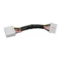
TOTAL CONTROL HARNESS INSTALLATION
PIC 1
USE THIS HARNESS
TOP TRIPLE TREE
BOTTOM OF RADIO
FAIRING BRACE
FIG 1
THIS FIGURE FOR WIRE
COLOR AND PIN LOCATION
 Loading...