The stock backing plate may now be removed from the motorcycle, and the tank may now be returned
to its original position and re-connected. The stock backing plate will be able to be removed by just
holding up on the back side of the fuel tank, but it will be a tight fit.
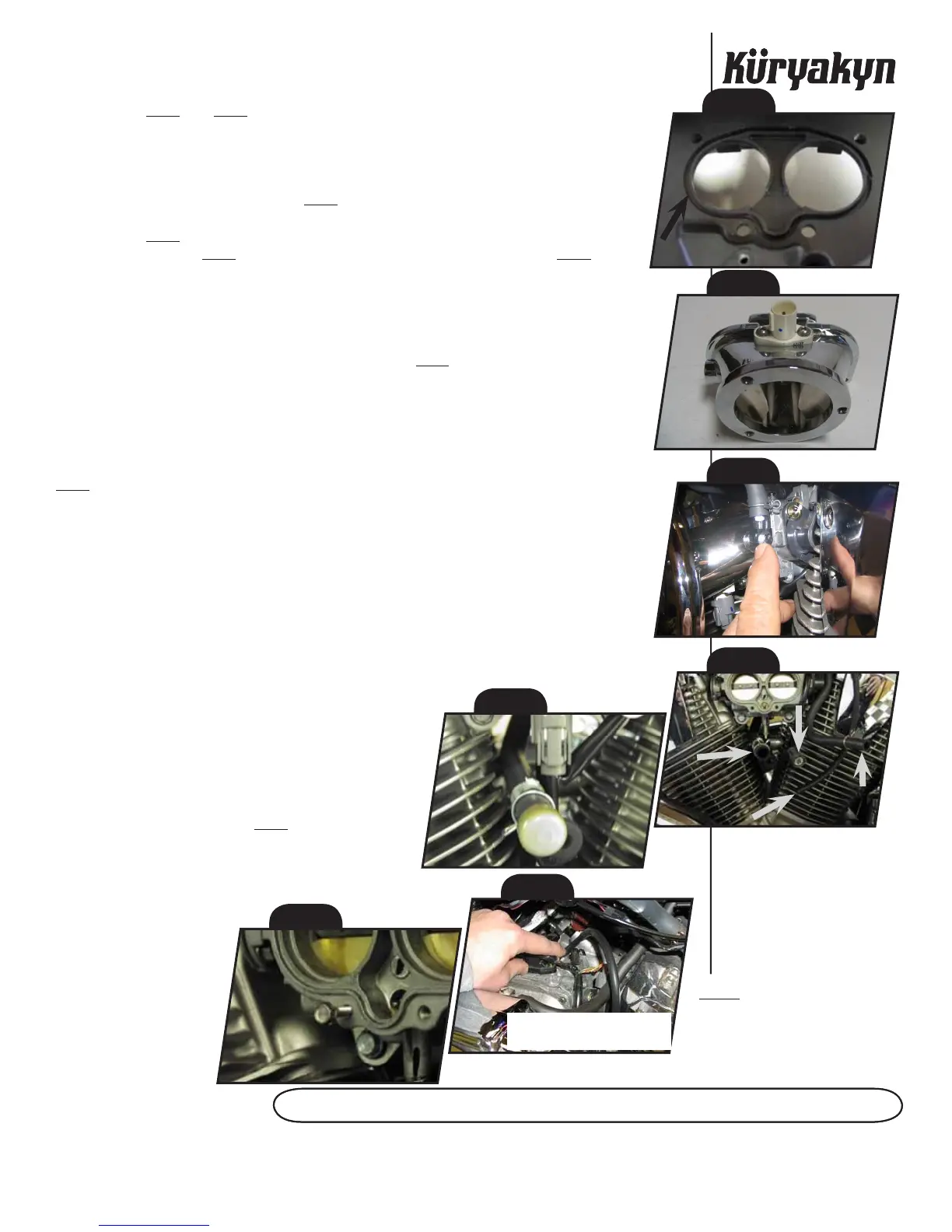
See PIC.2, and PIC.3. Remove the white plastic air mass (temp) sensor and the O-ring
from the stock backing plate. Install the O-ring into corresponding groove in the new cast throttle
body adapter. Install the air mass sensor into the adapter at this time using the 10 x 24 B.S.C.H.
Install the chrome elbow into the manifold then the nipple into the elbow. Make sure to point the
nipple up. Your crank case ventilation hose should be rerouted over the top of the throttle body
so it can be plugged into this nipple. See PIC.4.
See PIC.5. The largest diameter hose (marked as A) will be capped off using the vinyl
cap included in the kit. (PIC.6) The mass air sensor plug (marked as D) is shown in PIC.5. The
intermediate size hose (marked as B, about 3/8” I.D.) will be plugged into the nipple you have
installed on the throttle body adaptor (this is your crankcase breather). Follow the vacuum line
down from the cold start sensor, under tank, to where it connects to the vacuum nipple at the top
of the intake manifold between the two cylinders. Remove the hose from that vacuum nipple and
plug with the 1” pin supplied then stow under tank. Plug the 14” section of hose included with the
Hypercharger kit to the intake manifold nipple as shown in PIC.7. The smallest hose (marked as C
— approximately 1/4” outside diameter) is the hyper vacuum hose. The remaining end will later
be connected to the vacuum pod on the Hypercharger in STEP 7. DO NOT REUSE ANY OF THE
STOCK VACUUM LINES OR THE “T” FITTING OR THE BUTTERFLIES WILL NOT OPERATE. USE
A WIRE TIE TO SECURE THE DISCONNECTED STOCK VACUUM LINES.
This step will require some patience as you will be working in a very limited space. See
PIC.8. Start one of the M5 hex flange bolts in one of the two lower mounting holes of the throttle
body. Slide a corresponding slot on the throttle body adapter on to this bolt. Start the remaining
three bolts in the adapter mounting holes. Screw the BOTTOM two mounting screws in all the
way — it may be easier for you to hold the adapter out away from the throttle body as you run
these screws in. You will most likely have to use your open-end wrench and move the fasteners
about 1/6 of a turn at a time. Once the bottom two screws are in all the way, but not tightened,
you may thread the top two mounting screws in. Tighten all four screws, but do not over tighten
— if you snap or strip one of these screws, you will have to repeat this process.
Separate the two halves of the Hypercharger body and remove the filter element. A
5/32” Allen wrench will be used to remove the three “Flat head” Allen bolts on the outer cover
of the Hypercharger, and a 7/64” Allen wrench is used to remove the fasteners from the bearing
cups on the top and bottom of the butterfly shaft. Once you
have mounted the back plate to the throttle body adapter
using the three fasteners provided in the assembly, replace
the filter element, and reassemble the Hypercharger.
Connect the vacuum line to the nipple on the
bottom of the vacuum pod on the back of the Hypercharger
with the small hose marked C in PIC.5.
Ride On!
A
C
D
B
Vacuum Source for Hyper
Vacuum Supply
 Loading...