Kurz Instruments Inc. December 13, 2007
360210-AH Rev.A 504/534FTB Installation AH - 4
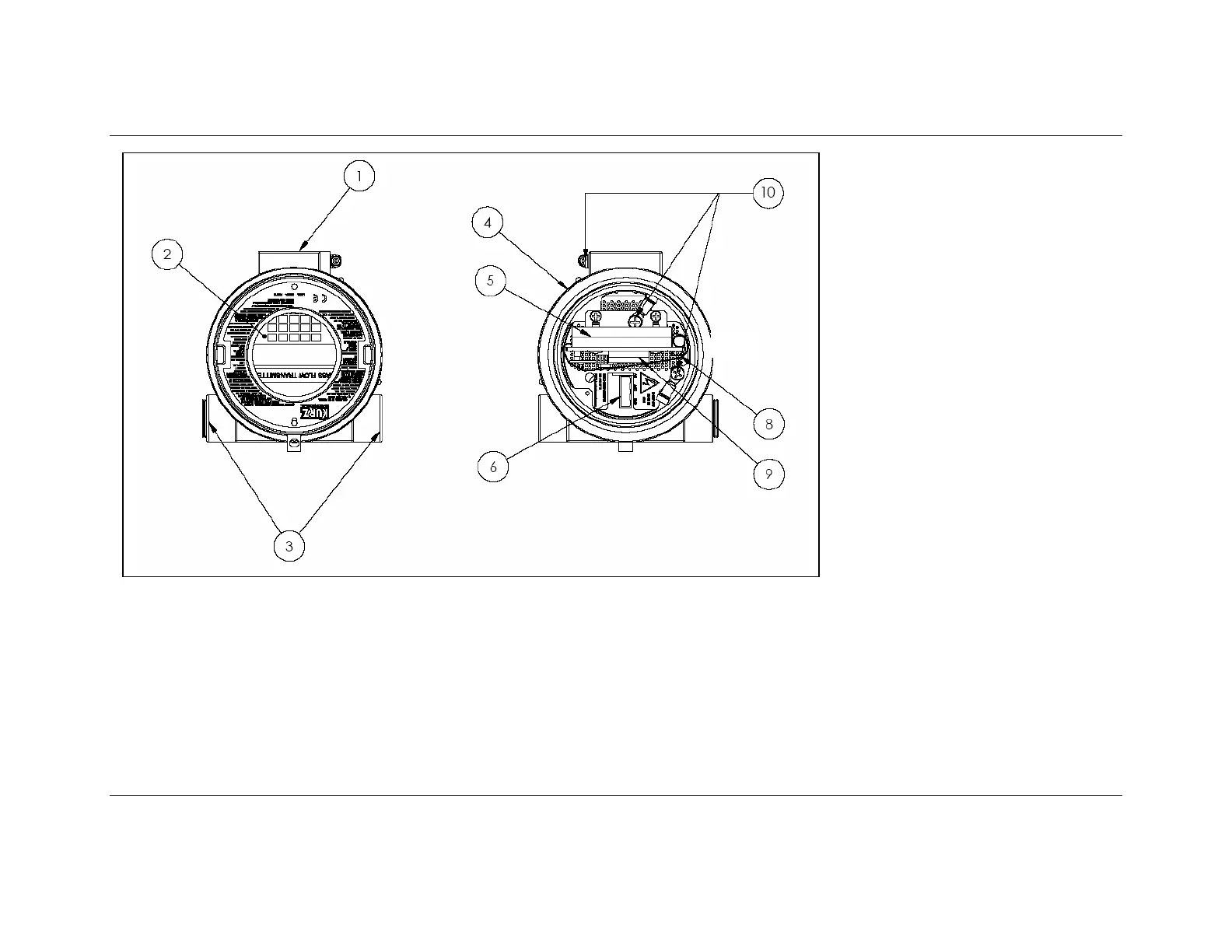
1. ¾” FNPT Sensor support port
(TA or Transmitter Attached
version)
Conduit or cable port (TS or
transmitter separate version)
2. Backlit 2x16 LCD and 20 key
button interface
3. ¾” FNPT signal and power
conduit ports.
4. Safety Label and Product ID
tag.
5. Main I/O wiring terminal block
for sensor, power, RS-485 and
4-20 mA outputs, TB1
6. AC power input. 85 to 265
VAC 50/60 Hz. 1 phase.
7. Power indicator: Green LED,
right side of TB1
8. USB mini-B connector
9. Optional hardware, AI, DO, DI,
Purge valve, I/O connector
TB6
10. External and internal ground
lug locations. Shielded wire
pig-tail termination location.
Figure AH-2. Location of major components
 Loading...