Table 4 Standing energy losses
System ref Heat loss Energy loss
(1)
maximum daily
(W) (kWh)
125 95 2.28
150 100 2.40
200 113 2.71
(1) These figures relate to a 45°C differential between the stored water and
ambient temperature.
Design Data
4 General
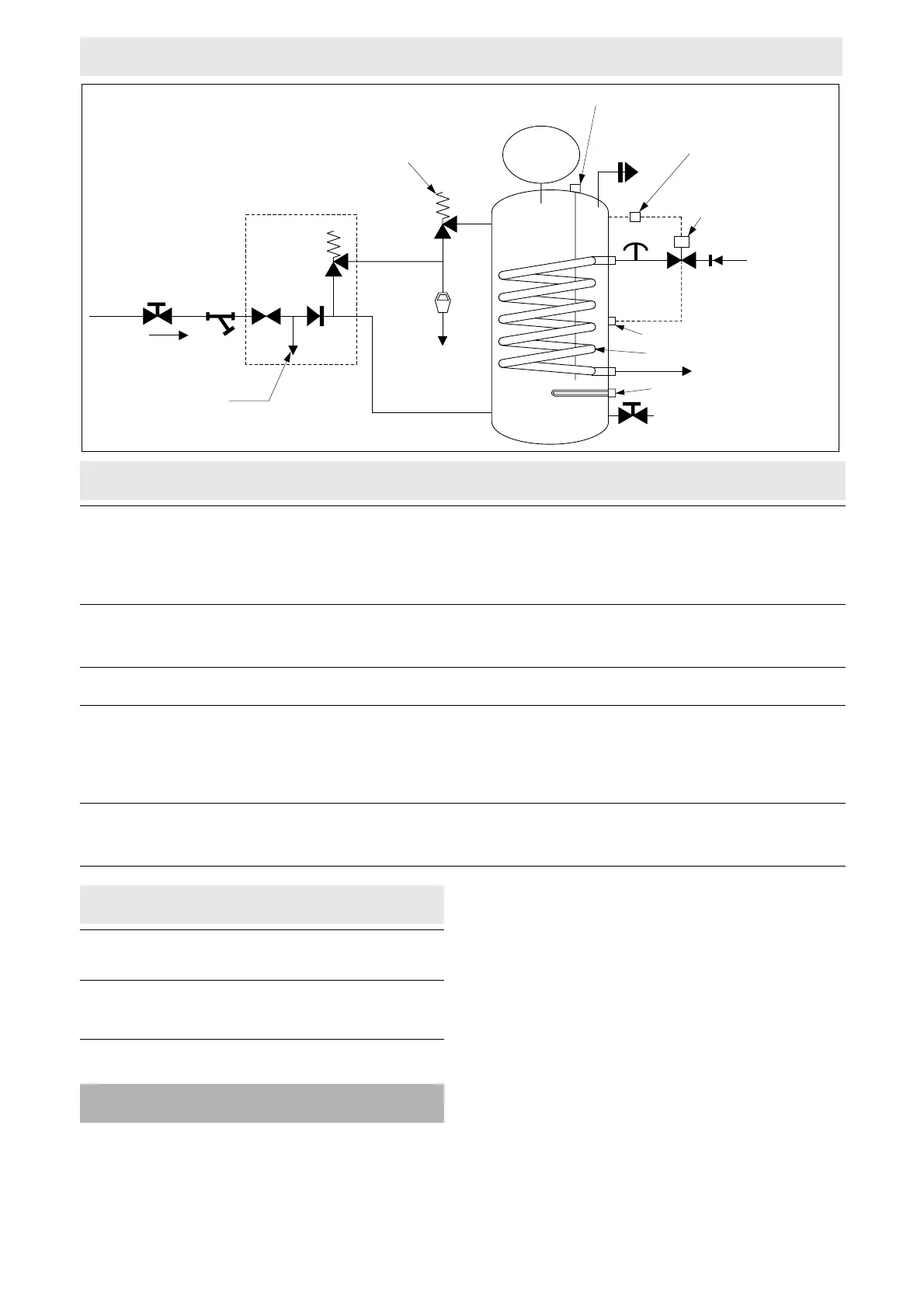
4.1 The Kwikot Indirect Unvented Hot Water
Storage System (see Figure 2) has been assessed
in accordance with MOAT No 38 : 1986. When
used in accordance with this Detail Sheet the
system will perform in a safe and satisfactory
manner.
4.2 The hot water system capacity, should be
selected in accordance with the recommendations
of BS 6700 : 1997, to meet the demands made
upon the installation. The primary circuit pipework
associated with indirect heating systems should be
designed in accordance with BS 6700 : 1997
and BS 5449 : 1977. Particular consideration
should be given to the inclusion of a primary circuit
by-pass to prevent excessive pressure on the
motorised valve and also safeguard against
‘nuisance tripping’ of the non-self-resetting thermal
cut-out.
4.3 The pressure and flow available from the
water mains should be obtained from the local
water undertaker or by testing existing supplies to
3
Figure 2 Schematic layout — Indirect
Table 3 Heating, re-heating and water draw-off temperature
Indirect heating
AB CD
System Primary flow Heat-up Percentage of the capacity Mean Re-heating
ref time
(1)
and amount drawn off within draw-off time
10°C of set temperature temperature
(litres per minute) (minutes) (%) (litres) (°C) (minutes)
125 15 27 89 111 60 21
150 15 34 91 136 60 26
210 15 45 93 186 60 30
(1) These heat-up times apply to a pumped system only and assume a boiler of adequate output is connected to the system. Primary flows of 15 litres per
minute normally can be attained with a standard domestic circulating pump.
Direct heating
AB CD
System Heat source Heat-up Percentage of the capacity Mean Re-heating
ref time and amount drawn off within draw-off time
10°C of set temperature temperature
(kW) (minutes) (%) (litres) (°C) (minutes)
125 3 160 89 111 60 105
150 3 187 90 135 60 152
210 3 250 93 195 60 177
 Loading...