establish the likely performance of the system at
peak periods.
4.4 It is essential, for reasons of safety and
performance, that installation of the system is
undertaken only by a
competent person
working
in accordance with this Detail Sheet.
4.5 The data shown in Tables 3 and 4
represent the analysis of tests carried out by the
BBA.
5 Hot water storage and supply
Hot water storage
5.1 The capacities of the system range are
comparable with conventional systems (see
Table 1). When heated to 60°C the system can
supply 70% of the storage capacity at the mean
temperature given in Table 3.
Flow rates
5.2 The flow rates achieved at the hot water
draw-off point will depend on all the normal
factors including the layout of the pipework from
the tap to the cylinder, the cold water supply
pressure and the flow rate available at the supply
to the system.
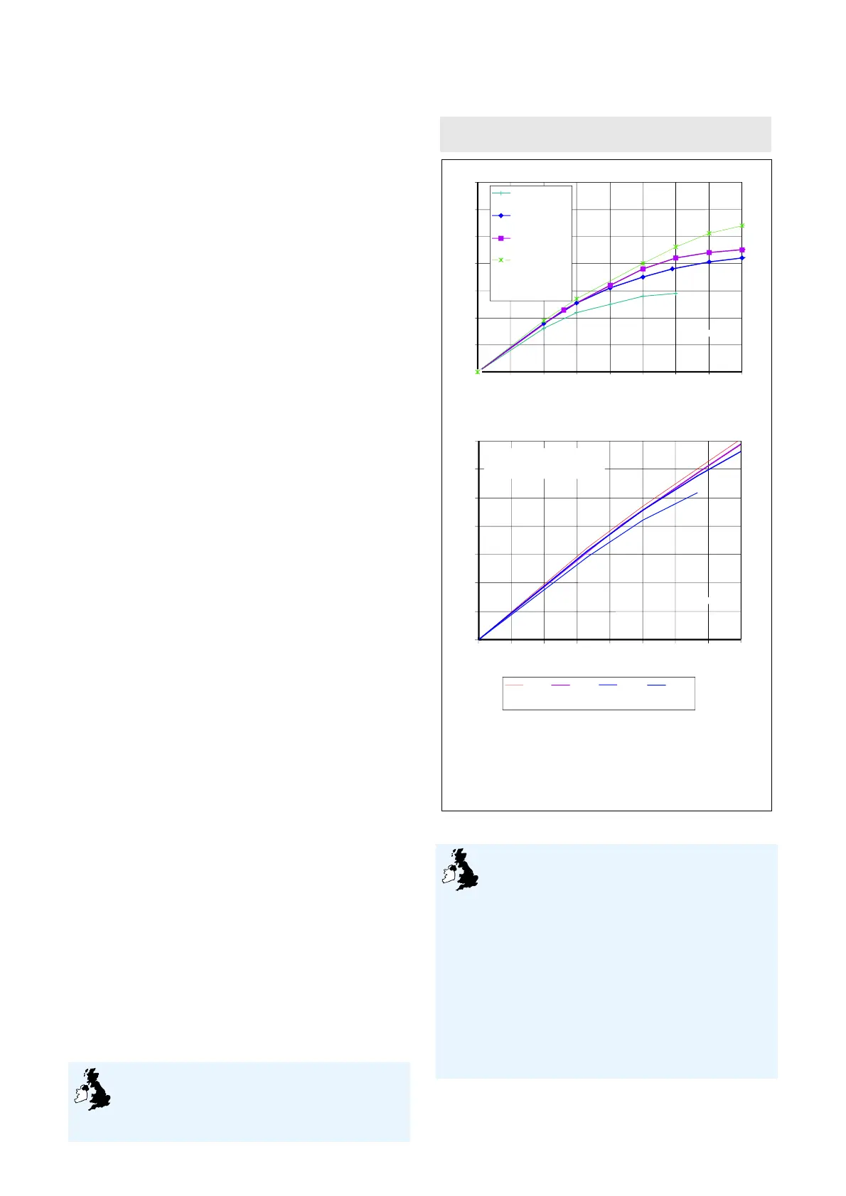
5.3 For design purposes the graphs in Figure 3
show the relationship between:
• flow available
• mains supply pressure, and
•
the maximum hot water flow rate out of the
system
(1)
.
(1) Flow characteristics shown in the graphs reflect the worst
combination of cold water control components that may
be installed (see Detail Sheet 2).
5.4 The hot/cold mixed flows are for draw-off
temperatures of 40°C (assume 60% at 60°C and
40% at 10°C).
Heat-up, re-heating and hot water draw-off
temperature
5.5 The heat-up and re-heat times are comparable
with conventional systems of a similar size
supplying hot water.
5.6 The immersion heater will heat the stored
water from 15°C to 60°C in the time listed in
column A of Table 3.
5.7 The amount of water that can be drawn off
within 10°C of the set temperature is listed in
column B of Table 3, the mean temperature of
70% of the water drawn off immediately after
reaching 60°C in column C, and the time taken
to re-heat the stored water to 60°C in column D.
Temperature control
5.8 The thermostats wired to the
immersion heater and motorised valve are
satisfactory for controlling the temperature
of the stored water.
Pressure control
5.9 The pressure control valve is satisfactory for
controlling the pressure of the water supplied from
the water mains or other suitable potable supply.
Figure 3 Flow rates
Insulation
5.10 The system is provided with
adequate insulation to satisfactorily limit
the energy loss from the stored water and
meets the requirements described in the national
Building Regulations:
England and Wales
Approved Document L1
Scotland
Regulation 22, Standard J3.4
Northern Ireland
Technical Booklet F, Paragraph 3.3.
5.11 The heat loss of each system while
maintaining the temperature of the stored water at
65°C is shown in Table 4.
0
10
20
30
40
50
60
70
0
10
20 30 40 50 60
70
80
2 bar
3 bar
4 bar
8 bar
Static supply pressures
of incoming water
supply
flow available (lmin ) at entry to system
–1
flow out (lmin ) of the system
–1
hot only
¾" valves
0
10
20
30
40
50
60
70
0 1020304050
60 70 80
flow available at entry to the system(lmin )
–1
8 bar 4 bar 3 bar 2 bar
Static supply pressures of incoming water supply
flow out (lmin ) of the system
–1
• Flow rates shown apply to situations where the supply is capable of supplying an
adequate dynamic pressure.
• The graph represents the results of tests carried out by the BBA.
• Where static water supplies are less than 1 bar, consult Kwikot Limited or the BBA.
• Flow rates shown for mixed hot/cold water assume that the cold supply is not
taken from the balanced connection of the pressure reducing valve
Notes
hot/cold mixed
mixed water at 40ºC, mixed from
60% hot water at 60ºC and
40% cold water at 10ºC
¾" valves
 Loading...