EasyManua.ls Logo

KYE Systems Corp. Genius SW-5.1 1505 - User Manual

Default Icon
17 pages
Print Icon
To Next Page IconTo Next Page
Loading...
Service Guide SW-5.1 1505
Version : 1.0 Page 1 of 17
SERVICE GUIDE
KYE SYSTEMS CORP.
SW-5.1 1505
Question and Answer IconNeed help?

Do you have a question about the KYE Systems Corp. Genius SW-5.1 1505 and is the answer not in the manual?

Summary

Revision History

Getting Started

Conventions Used in this Guide

Explains symbols and notes used throughout the guide to prevent mistakes and damage.

Safety Precautions

Details precautions for handling speakers, including environment, handling, and maintenance.

Chapter 1. How to Handle Defective Returns

1.1 Overview

Provides a flowchart illustrating the process for handling defective speaker returns from customers.

One or more channels no sound

Troubleshooting guide for identifying and resolving issues with missing audio channels in the speaker system.

Wired Control no function

Steps to diagnose and fix problems where the wired control unit of the speaker system is not responding.

Power LED (indicator) no light

Guide to troubleshoot why the power indicator LED on the speaker system is not illuminating.

Volume, Bass no function

Procedures for diagnosing and repairing issues where volume or bass controls are unresponsive.

Chapter 2. Specifications

Chapter 3. Block Diagram

Chapter 4. Exploded View

Chapter 5. Part List

Chapter 6. Schematic Diagram

Chapter 7. Important Notes

Overview

This document is a service guide for the KYE Systems Corp. SW-5.1 1505 speaker system. It provides comprehensive information for handling defective returns, technical specifications, block diagrams, exploded views, part lists, schematic diagrams, and important notes for maintenance and repair.

Function Description

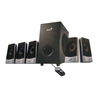
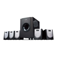
The SW-5.1 1505 is a 5.1 channel speaker system designed to provide surround sound. It consists of a subwoofer, a center speaker, and five satellite speakers (front left, front right, surround left, surround right). The system includes a wired control box for managing volume and bass levels. Audio input is processed through a power amplifier, which then distributes the amplified sound to the respective speaker units. A transformer and rectifier circuit handle the power supply for the system.

Important Technical Specifications

The speaker system's specifications are detailed for the Woofer, Center, and Satellite units:

Woofer:

  • Out Power at THD 10%: ≥ 17 W
  • Sensitivity: 130 ± 30 mV
  • Freq. Response (Top -3dB): 30 ~ 150 ± 10% Hz
  • S/N ratio: ≥ 70 dB
  • Hum & Noise (Vol.: max): ≤ 2 mV
  • Loud speaker: 4" 4 ohm 20W

Center Speaker:

  • Out Power at THD 10%: ≥ 6 W
  • Sensitivity: 550 ± 50 mV
  • Freq. Response (Top -3dB): 100 ~ 20K ± 10% Hz
  • S/N ratio: ≥ 70 dB
  • Hum & Noise (Vol.: max): ≤ 2 mV
  • Loud speaker: 3” 4 ohm 6W

Satellite Speakers (Front Left, Front Right, Surround Left, Surround Right):

  • Out Power at THD 10%: ≥ 6 W
  • Sensitivity:
    • FL,FR: 650 ± 60 mV
    • SL,SR: 500 ± 60 mV
  • Freq. Response (Top -3dB):
    • FL,FR: 70 ~ 20K ± 10% Hz
    • SL,SR: 80 ~ 20K ± 10% Hz
  • Separation: ≥ 40 dB
  • S/N ratio: ≥ 70 dB
  • Hum & Noise (Vol.: max): ≤ 2 mV
  • Loud speaker:
    • Front: 3” 4 ohm 6W
    • Surround: 3” 4 ohm 6W

General Components:

  • ICs: STA540SA (2 pcs), UTC4558 (3 pcs), PT2325-D (1 pc), L7809CV (1 pc)
  • Transformer: Available in 120V, 230V, and 240V versions, all 12VAC & 2.5A.
  • PCBA: SW-5.1 1505 specific.
  • Cables: Audio cables (3.5mm to RCA jack in green, orange, blue), 3 pin cable.

Usage Features

The SW-5.1 1505 speaker system is designed for ease of use with a wired control box that allows users to adjust the main volume and bass levels. The system accepts audio input via standard audio cables. The power LED indicates the operational status of the device.

Maintenance Features

The service guide provides detailed procedures and considerations for maintaining and repairing the SW-5.1 1505 speaker system:

Troubleshooting Flowcharts: The manual includes flowcharts for common problems, guiding technicians through diagnosis and rectification:

  • One or more channels no sound:
    • Causes: Broken or short circuit, defective ICs (U1-U7, VR1, VR2), wired control cable issues, PCBA connect cable issues, speaker cable disconnect, or damaged speakers.
    • Solutions: Check solder points on PCB, check and replace defective ICs, re-connect speaker cables, or replace defective speakers.
  • Wired Control no function:
    • Causes: Broken or short circuit on PCBA, defective ICs (U1-U7, VR1), 3 pin cable disconnect or damaged.
    • Solutions: Check solder points on PCBA, check and replace defective ICs/VR1, re-connect or replace defective cable.
  • Power LED (indicator) no light:
    • Causes: Defective power switch or LED, defective D2-D5 POWER, R2, LED wired control cable, AC cord of transformer disconnected or defective.
    • Solutions: Re-solder or replace defective component(s).
  • Volume, Bass no function:
    • Causes: Broken or short circuit, defective VR1 (Volume) or VR2 (Bass).
    • Solutions: Check solder points on PCB, check and replace defective components.

Safety Precautions:

  • Place speakers on a flat, level, stable surface.
  • Avoid environments with mist, smoke, vibration, excessive dust, salty/greasy air, or corrosive gases/fumes.
  • Do not drop or jolt speakers.
  • Prevent objects from falling into the subwoofer's ventilator to avoid electric shock or fire.
  • Ensure adequate heat dissipation by placing the unit away from other equipment.
  • Disconnect the AC power cord before maintenance.
  • Do not perform maintenance with wet hands.
  • Prevent foreign substances (water, liquids, chemicals) from entering speakers during maintenance.

Packing Requirements for PCB Assembly:

  • PCB assemblies are sophisticated electronic circuit boards and require careful packing for shipping.
  • Each PCB assembly should be packed in a separate static-protecting bag to prevent damage from static electricity.
  • Reliable external packing is crucial to prevent loss or damage during transit.

Spare Parts Management:

  • In situations where spare parts are scarce for multiple speaker systems awaiting repair, it is recommended to salvage necessary parts from one system to repair others, maximizing the number of functional units.

The guide also includes detailed exploded views for the woofer, satellite speakers, and wired control box, along with a comprehensive part list and schematic diagrams, which are essential for identifying components and understanding the circuit layout during repair.

KYE Systems Corp. Genius SW-5.1 1505 Specifications

General IconGeneral
BrandKYE Systems Corp.
ModelGenius SW-5.1 1505
CategorySpeaker System
LanguageEnglish

Related product manuals