Do you have a question about the KYE Systems Corp. Genius SW-5.1 1010 and is the answer not in the manual?
This document is a service guide for a speaker system, likely a 5.1 channel setup, manufactured by KYE SYSTEM CORP. The guide provides information for servicing and troubleshooting the device, including specifications, block diagrams, exploded views, part lists, and schematic diagrams.
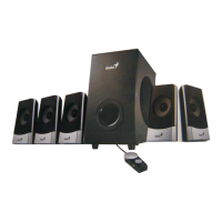
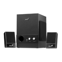
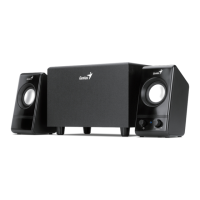
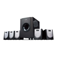
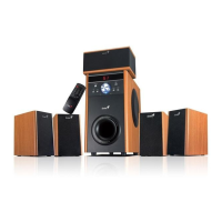
The device is a multi-channel speaker system, indicated by the 5.1 channel references in the part list and the presence of front, rear, center, and subwoofer components. It includes a main subwoofer unit, satellite speakers, and a remote control. The system is designed to produce audio output, likely for entertainment purposes such as home theater or gaming. The block diagram shows inputs for stereo, front, rear, and center/subwoofer audio, which are processed through a master volume control (BT2258) and an MCU control (MK6A11P). The audio signals are then amplified by TEA2025B for the woofer and BT2025B for the satellite speakers before being output to the respective speaker units. The remote control allows for wireless operation of the system.
The service guide provides detailed specifications for both the satellite speakers and the subwoofer.
Satellite Speakers:
Subwoofer:
The device is a speaker system that requires proper setup and handling. The guide emphasizes safety precautions, such as placing speakers on a stable surface, avoiding extreme environments (mist, smoke, vibration, excessive dust, corrosive gases), preventing drops or jolts, and ensuring good heat dissipation. It also warns against allowing foreign substances into the subwoofer's ventilator to prevent electric shock or fire. Maintenance should not be performed with wet hands.
The system includes a remote control for operation, which is covered in the troubleshooting section. Issues like "No power, LED (indicator) no light," "No sound" from various channels (front, rear, woofer, center), "Noise," "LED indicators no light," and "Remote control not work, volume switch no use" are addressed with flowcharts for diagnosis and repair.
The service guide is primarily focused on maintenance and repair procedures. It outlines a systematic approach to handling defective returns, starting with verifying problems, analyzing malfunction causes, deciding on rectification methods, replacing necessary defective parts, and then verifying the repair.
Troubleshooting Flowcharts: The guide provides detailed flowcharts for common problems, including:
Packing Requirements for PCB Assembly: The guide emphasizes the importance of proper packing for PCB assemblies when sending them by post. This includes using separate static-protecting bags for each PCB to prevent static electricity damage and ensuring reliable external packing to avoid loss or damage during transit.
Spare Parts Management: For situations where spare parts are scarce, the guide suggests taking necessary parts from one speaker system to repair others, maximizing the number of functional speaker systems.
The document also includes detailed exploded views and part lists for the subwoofer, satellite speakers, and remote control, which are crucial for identifying and ordering replacement parts during maintenance. Schematic diagrams for the input and MCU PCB, SATAMP PCB, and SWAMP PCB provide circuit-level details for advanced troubleshooting and repair.
| Brand | KYE Systems Corp. |
|---|---|
| Model | Genius SW-5.1 1010 |
| Category | Speaker System |
| Language | English |