Do you have a question about the Kyosho V-one RRR and is the answer not in the manual?
Key safety guidelines for handling and operating the RC model, emphasizing caution and responsible use.
Details on the required 2-channel radio control set, including transmitter types and servo compatibility.
Specifications for the required 12-class engine, muffler, manifold, and plug. Notes on compatibility.
List of necessary items for starting the engine, including fuel, fuel pump, plug heater, and starter.
Information on paints required for body finishing and Kyosho's available model paints.
Listing of any additional equipment needed for the model's operation or maintenance.
Step-by-step guide for setting up the radio transmitter and receiver, including battery installation and antenna extension.
Explanation of manual symbols, diagrams, and how to read instructions for effective assembly.
Guide to common symbols and their meanings throughout the assembly instructions.
Details on identifying different types of screws, nuts, and small parts included in the kit.
Detailed instructions for assembling the gear differential, including part numbers and specific hardware.
Instructions for assembling the front oneway unit, noting part usage and glue application points.
Installation of the servo saver, detailing screw and ball end installations.
Instructions for connecting the steering rods, specifying screw, ball end, and metal bushing usage.
Detailed steps for assembling the front suspension arm for the right side, including hardware and bush placement.
Detailed steps for assembling the front suspension arm for the left side, including hardware and bush placement.
Assembly of the front suspension arm, specifying suspension bush types and their placement.
Assembly of the front suspension arm and adjustment of belt tension, noting part orientation.
Instructions for assembling the steering rod linkage, including ball end and reverse screw details.
Detailed steps for assembling the knuckle arm, including ball studs, bearings, and nylon nuts.
Assembly of the front suspension arm, connecting steering rods and ensuring smooth movement.
Steps for assembling the front shock absorbers, including shock collars, pistons, and O-rings.
Instructions for assembling the front shock absorber, specifically the short version for front use.
Assembly of the front shock stay, detailing screw and flange ball connections.
Instructions for attaching the front bumper, specifying screw and nut usage.
Assembly of the rear bulkhead, including the brake piston and shaft, with notes on part orientation.
Assembly of the rear bulkhead, focusing on the spur gear shaft and pulley installation.
Assembly of the rear bulkhead, involving bearing installation and specific part orientation.
Assembly of the rear bulkhead, including ball end and adjustable rod connections, noting part insertion direction.
Assembly of rear bulkhead, differential, and belt tension adjustment, noting inscriptions and part orientation.
Assembly of the rear bulkhead and lower suspension arm, including suspension bush placement.
Instructions for assembling the rear hub, including pillow balls, wheel shafts, and screw caps.
Assembly of rear bulkhead with drive components like pins, pulleys, and bearings.
Steps for assembling the rear stabilizer, involving ball ends, set screws, and ball stoppers.
Assembly of the rear stabilizer and its mounting to the chassis, noting part orientation.
Detailed instructions for assembling the 2-speed changer, including set screws, rollers, and springs.
Assembly of the 2-speed changer gears, detailing screw and bearing installations.
Instructions for assembling the rear shock absorbers, including ball ends, collars, and pistons.
Assembly of the rear shock absorber, specifically the long version for rear mounting.
Guidance on mounting the rear shocks, referencing the setting data sheet for precise positioning.
Instructions for attaching the middle shaft support, specifying screw usage.
Assembly of the middle shaft support, including belt drive components like pulleys and bearings.
Instructions for assembling the center bulk, detailing screw, nut, and washer usage.
Guidance on installing the battery, including recommended battery types and securing methods.
Instructions for assembling and mounting the fuel tank, specifying screw and O-ring usage.
Steps for installing the receiver, including antenna cord routing and cutting shaded portions.
Installation of the servo saver for the steering servo, emphasizing rubber grommet usage.
Installation of the servo saver for the throttle servo, emphasizing rubber grommet usage.
Assembly of various linkages and preparation of fuel tube, including bending and cutting.
Installation of the radio plate, connecting servo linkages and managing antenna/control cords.
Mounting the radio plate and installing the switch component.
Installation of the radio plate, connecting steering and throttle servos.
Preparation of the engine, focusing on pilot nut washer installation for proper clearance.
Assembly of engine components, including bell guide washers, bearings, and shims for clearance adjustment.
Mounting the engine and ensuring correct gear engagement with a paper shim for clearance.
Assembly of the muffler and manifold, with instructions for bending the wire to adjust the muffler position.
Securing the muffler using set screws and ensuring proper fitment.
Installation of the rear stiffener, specifying screw usage.
Routing of the fuel tube using silicone tubes for proper connection to the engine.
Installation of the air cleaner onto the engine.
Installation of the wheels and the use of flanged nylon nuts for securement.
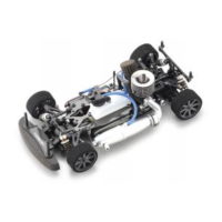
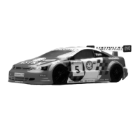
Mounting the body shell and general safety precautions for running the model.
Essential safety guidelines and warnings for operating the RC model, covering fuel, engine heat, and environment.
| Scale | 1/10 |
|---|---|
| Class | On-Road |
| Transmission | 2-speed |
| Suspension | Double Wishbone |
| Drive System | Shaft Drive |
| Motor | Not included |
| Required Equipment | glow igniter |