EasyManua.ls Logo

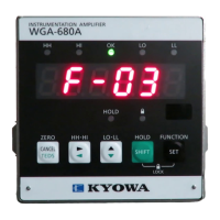
KYOWA WGA-680A Series User Manual

Default Icon
61 pages
To Next Page IconTo Next Page
Page #1 background imageLoading...
Page #1 background image
IM-A-1048H April 2019
INSTRUCTION MANUAL
WGA-680A
INSTRUMENTATION AMPLIFIER
Thank you for purchas ing KYOWAs product WGA-680A Instrumentation
Ampli fier.
Read this Instruction Manual carefully in order to make full use of the high
performance capabilitie s of the product.
Do no t use the product in methods other than described in this Manual.
Generally, c ompany names and trade names described in this Instruction Manual are trade marks or registered
trademarks of the companies.
This Instruction Manual may not be copied or reproduced, in whole or part, without consent of KYOWA.
Copyright © Kyowa Electronic Instruments Co., Ltd. All rights reserved.
The contents of the Instruction Manual are subjected to change without prior notice.
We assume no responsibility whatever for any damage resulting from the use of this product.

Questions and Answers:

KYOWA WGA-680A Series Specifications

General IconGeneral
BrandKYOWA
ModelWGA-680A Series
CategoryAmplifier
LanguageEnglish

Summary

1. OUTLINE OF PRODUCT

1-1. Outline

General description of the WGA-680A Instrumentation Amplifier.

1-2. Features

Lists key features and capabilities of the WGA-680A.

1-3. Model

Details the different WGA-680A models and their specifications.

SAFETY PRECAUTIONS

Prior to Use

Important information and symbols for safe operation before using the product.

LIMITED LIFE PARTS AND PREVENTIVE MAINTENANCE

Replacement Before End of Service Life

Recommendations for product replacement and preventive maintenance.

Notations Used in Manual

Explains notations used in the manual for clarity and reference.

IMPORTANT PRECAUTIONS WHEN USING WGA-680A

CE Marking Precautions

Safety and installation precautions related to CE marking requirements.

2. CONTROLS AND FUNCTIONS

2-1. Front Panel

Details the controls and indicators on the front panel of the WGA-680A.

2-2. Rear Panel

Describes the connectors and terminals on the rear panel of the WGA-680A.

3. CONNECTION AND DEFAULT SETTING

3-1. Procedures for Measurements

Outlines the essential steps for connecting and preparing the WGA-680A for measurements.

3-2. Panel Mounting

Provides instructions and dimensions for panel mounting the WGA-680A unit.

3-3. Connecting Transducers

Instructions for connecting strain gauge transducers to the WGA-680A terminals.

3-4. Input Terminals

Details on connecting external switches or signals to the input terminals.

3-5. Output Terminals

Explains how to connect cables to the open collector output terminals.

3-6. Analog Output Terminals

Instructions for connecting analog output signals (voltage or current).

3-7. Power Supply Connection

Procedures for connecting AC and DC power supplies to the WGA-680A unit.

4. OPERATIONS AND FUNCTIONS

4-1. Key Operations

Details key operations, including lock function and measuring mode interactions.

4-2. Bridge Excitation Voltage Selection

How to select and set the bridge excitation voltage for transducers.

4-3. Digital Zero Function

Function to set the display to zero, with key and rear panel operations.

4-4. CALIBRATION FUNCTION

Covers actual load, sensitivity, and numeric value calibration procedures.

4-5. COMPARATOR FUNCTIONS

Explains comparator functions, settings, and output conditions.

4-6. Pattern Function

Registering and selecting limit values in 4 operation patterns.

4-7. Level Test Function

Function for adjusting external devices or testing output using pre-set values.

4-8. Updating Rate of Displaying Values

Adjusting the display update rate for easier reading of changing values.

4-9. Display Stability Function

Function to reduce variations in displayed values.

4-10. HOLD FUNCTIONS

Details various hold modes, operations, and settings.

4-11. Analog Output (D/A) Function

Converts measured values to analog output signals (voltage or current).

4-12. List of Functions

Lists and categorizes various functions accessible via the FUNCTION SELECTING mode.

5. OPERATION TIMING

5-1. Control Input Signals

Timing diagrams for control input signals like HOLD, RESET, and ZERO.

5-2. Comparator Outputs

Timing and hysteresis for comparator outputs (HI, LO).

5-3. Delay Time Between Input and Output Signals

Specifies the maximum delay time for analog output.

6. TROUBLE SHOOTING

7. MAINTENANCE

Calibration of Apparatus

Recommends annual maintenance inspection and calibration of the apparatus.

Replacement of Consumable Parts

Information on consumable parts and recommended overhaul periods.

8. SPECIFICATIONS

9. OUTSIDE DRAWING

9-1. WGA-680A -00: No option (AC model)

Shows the external dimensions and connection points for the AC model.

9-2. WGA-680A -10: No option (DC model)

Shows the external dimensions and connection points for the DC model.

Related product manuals