EasyManua.ls Logo

KYOWA WGA-910A Series User Manual

KYOWA WGA-910A Series
150 pages
To Next Page IconTo Next Page
Page #1 background imageLoading...
Page #1 background image
IM-A-1140 Oct 2017
INSTRUCTION MANUAL
WGA-910A
INSTRUMENTATION AMPLIFIER
Thank you for purchasing KYOWAs product WGA-910A Instrumentation
Amplifier.
Read this Instruction Manual carefully in order to make full use of the high
performance capabilities of the product.
Do not use the product in methods other than described in this Manual.
Generally, company names and trade names described in this Instruction Manual are trademarks or registered
trademarks of the companies.
This Instruction Manual may not be copied or reproduced, in whole or part, without consent of KYOWA.
Copyright © Kyowa Electronic Instruments Co., Ltd. All rights reserved.
The contents of the Instruction Manual are subjected to change without prior notice.
Please follow the safety precautions and other precautions described in this manual.
Question and Answer IconNeed help?

Do you have a question about the KYOWA WGA-910A Series and is the answer not in the manual?

KYOWA WGA-910A Series Specifications

General IconGeneral
Rated Output Voltage±10 V
Frequency ResponseDC to 100 kHz
Input Impedance1 MΩ
Power Supply±15V DC
Input Voltage Range±10 V
Operating Temperature Range0 to 50°C
Gain Range1 to 1000
Common Mode Rejection Ratio80dB
Noise5μVrms
Weight300g

Summary

Standard Accessories

Optional Equipment

Safety Precautions

Safety Symbols

Explains safety symbols used in the manual to highlight potential hazards.

General Warning Precautions

Power Supply Safety

Ensures correct power supply voltage and connection to prevent fire hazards.

Power Cable and Outlet Safety

Details safe practices for connecting power cables and using grounding terminals.

Protective Grounding

Ensures proper grounding to prevent electric shock hazards.

Electrical Operator Safety

Cautions operators against altering protective grounding conductors or disconnecting terminals.

Confirming Protective Ground

Instructs to check protective ground function before operation for safety.

External Connection Safety

Ensures safe grounding of external instruments before connecting to the WGA-910A.

Fuse Safety

Explains fuse function and advises contacting KYOWA for replacements.

Inflammable Environment Precautions

Warns against operating in environments with flammable gases, vapors, or dust.

Handling Malfunctions

Details immediate actions if smoke occurs from the WGA-910A.

Maximum Input Voltage Range

Specifies limits for input voltage to prevent damage and performance degradation.

Built-in Lithium Battery Safety

Provides safety instructions for handling the internal lithium battery.

General Cautionary Precautions

Outdoor Usage Prohibition

Warns against using the product outdoors due to potential hazards and performance issues.

Power Cycling Precautions

Advises waiting 5 seconds after power OFF before turning ON to prevent product damage.

Operating Temperature Range

Specifies the safe operating temperature range of -10 to +40°C.

Operating Humidity Range

Specifies the safe operating humidity range of 20 to 85% RH.

Environmental Change Adaptation

Recommends allowing the product to adapt to environmental changes to prevent condensation.

Vibration and Impact Precautions

Warns against excessive vibration or impact which can degrade performance or cause failure.

Electromagnetic Field Interference

Advises avoiding strong electromagnetic fields that may affect performance.

General Operating Condition Precautions

Covers power supply stability, noise, and avoiding cord strain.

Product Disassembly Prohibition

Prohibits disassembly or remodeling to prevent electric shock or damage; voids warranty.

Dust and Corrosive Environment Precautions

Warns against use or storage in dusty, particle-filled, or corrosive gas environments.

Sea Air Exposure Precautions

Warns against exposing the product to sea air which may cause performance issues.

CD-R Handling Precautions

Provides guidance on handling the CD-R to prevent damage or read errors.

Product Preheat Procedure

Recommends preheating the product for approximately 30 minutes before use.

Cleaning Instructions

Details how to clean the product using a dry cloth or air blow gun.

SD Card Compatibility Warning

CE Marking Precautions

CE Marking Installation and Wiring

Details installation, wiring, grounding, and environmental requirements for CE marking.

Manual Notations Guide

Panel Surface Notations

Explains how panel surface names are denoted in the manual.

Informational Notes

Describes notations used to attract attention to special care or reference information.

Notation Examples

Provides examples of how specific notations are presented in the manual.

Important Precautions for WGA-910A Use

Transducer Cable Break Output Behavior

Describes output behavior when the transducer cable is broken and advises countermeasures.

Output Signal and Load Requirements

Specifies requirements for the output signal's unbalance load (5k ohm or more).

Product Outline and Features

Product Overview

Provides a general description of the WGA-910A Instrumentation Amplifier.

Key Features

Lists the main features, including high-speed sampling, multiple calibration functions, and SD card capability.

WGA-910A Models

Controls and Functions Overview

Front Panel Controls and Displays

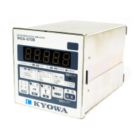
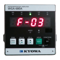
Identifies and describes the controls and displays on the front panel.

Measuring Window: Number Display

Details the 'Measuring Window' when displaying numerical values.

Measuring Window: Zoomed Number Display

Measuring Window: Waveform Display

Measuring Window: Cursor Functionality

Measuring Window: Dual Number Display

Measuring Window: Zoomed Dual Number Display

Measuring Window: Dual Waveform Display

Back Panel Overview

Back Panel Connectors

RS-232C Communication Interface

Details the pin assignment and function of the RS-232C connector.

Protective Grounding Terminal

Specifies the protective grounding terminal for safety.

Panel Mounting Metal Fitting

Describes the metal fitting used for panel mounting.

Monitor Terminal Board

Details the terminal board for monitor output and its function.

Control I/O Connector Details

Connection Procedures

Measurement Connection Procedures

Outlines the sequence of operations required before taking measurements.

Panel Installation Guide

Wiring Instructions

Transducer Connection

Details how to connect strain gage transducers to the input connector.

Connecting Control Input

Connecting Control Output

Connecting the RS-232C Interface

Monitor Output Connection

Connecting AC Power

Checking Power Voltage

SD Card Operations

Inserting the SD Card

Provides instructions for inserting an SD card into the WGA-910A.

Removing the SD Card

Provides instructions for safely removing the SD card from the WGA-910A.

Basic Operation Procedures

Setting Tree Overview

Illustrates the hierarchical structure of the WGA-910A's settings menu.

Configuring Display Windows

Basic Setting Operations

Operating Waveform and Cursor Windows

Saving Waveform Data

Explains the procedure and conditions for saving waveform data to the SD card.

Calibration Procedures

Calibration Methods Overview

Introduces the four calibration methods available: manual, TEDS auto, TEDS part, and numeric.

Calibration Workflow

How to Calibrate the Device

Accessing the Calibration Window

Explains how to navigate to the calibration window from the measuring screen.

Manual Input Calibration Steps

Details the steps for manual calibration, starting with bridge voltage and no-load zero.

Performing No-Load Zero Calibration

Sensitivity Registering Calibration

Actual Load Calibration Procedure

Setting Measurement Units

TEDS-based Automatic Calibration

TEDS Partial Calibration

Numeric Value Registering Calibration

Operation and Functions

Calibration Procedures Reference

Refers to Section 5 for detailed calibration methods like manual and TEDS.

Digital Zero Function Operation

Explains how to set the current display value to zero using key operation or external input.

TEDS Operation Settings

Zero During TEDS Setting

Allows selecting whether to conduct or prohibit no-load zero during TEDS reading.

TEDS Information Display

Explains how to read and display TEDS information on the window.

Input Setting Adjustments

Smoothing Function Settings

Explains smoothing using analog or digital methods to stabilize display values.

Minimum Scale Setting

Moving Average Filter Settings

Zero Compensation Function

Zero Tracking Operation

Automatically sets the display to zero within compensation range at set intervals.

Minimum Scale Zero Fix

Additional Value Setting

Displaying Original Sensor Output

Measuring Condition Settings

Selecting Measuring Conditions

Explains how to select measuring conditions via key operation, control input, or command.

Comparator Setting Configuration

Comparator Hysteresis Width Setting

Sets the width between comparator ON and OFF states to prevent chattering.

Comparator Output Logic Setting

Enabling/Disabling Comparators

Measure Mode Setting

Comparator Output Behavior and Status Lamps

Illustrates how comparator outputs and status lamps behave with hysteresis.

Operation Mode Descriptions

Block-Specified Peak and Bottom Modes

Time-Specified Peak and Bottom Modes

Block Averaging and Time Averaging Modes

Bottom Hold Operation Mode

Arbitrary Point Hold Operation Mode

Block and Time Peak-Bottom Modes

HOLD and RESET Command Operations

Comparator Relations and Statuses

Waveform Display Settings

Setting the Waveform X-axis

Configures the end point of the time axis (X-axis) for waveform display.

Setting the Waveform Y-axis

Wave Start Mode (Trigger Mode) Settings

Setting the Passed Level (Trigger Level)

Setting Level Passed Way (Trigger Slope)

Setting Hold Time of Wave

Initial Setting Configuration

Measuring Condition Selection Signal

Sets the signal used for selecting the measuring condition number.

System Settings

Key Lock Functionality

Allows locking or releasing the keys to prevent accidental changes.

System Settings Initialization

Backlight Timer Setting

Display Language Selection

Built-in Clock Adjustment

Device Self-Check Procedures

Memory Check Functionality

Checks the ROM, RAM, and EEPROM for faults to ensure memory integrity.

Sensor Input Channel Check

Operation Check Procedures

Display Functionality Check

Checks display color changes and backlight operation.

Touch Panel Operation Check

Verifies the responsiveness and functionality of the touch panel.

Control Input/Output Check

Communication Interface Check

BCD Output Check

D/A Output Check

SD Card Operation Check

SD Card Setting and Management

Saving Setting Values to SD Card

Saves all setting values, excluding calibration, to the SD card.

Reading Setting Values from SD Card

Reads setting values from the SD card and overwrites them on the WGA-910A.

Viewing and Managing Wave Files

Formatting the SD Card

Updating WGA-910A Firmware

Operation Timing Diagrams

Control Input Timing (HOLD, RESET, ZERO)

Illustrates timing diagrams for HOLD, RESET, and ZERO commands.

Block-Specified Command Timing

Time-Specified Command Timing

Comparator Output Timing

Input to Output Delay Time

Waveform Display and SD Signal Output

Waveform Display: Single Mode

Details waveform display and SD signal output timing in Single Mode.

Waveform Display: Auto and Normal Modes

RS-232C Communication

RS-232C Interface Specifications

Details the signaling system, data rate, parity, stop bit, and delimiter for RS-232C.

Control Command Overview

Explains the formats and types of control commands for external equipment.

Details of Control Commands

Initial Setting Commands

Describes commands for initializing settings, performing RS line tests, and outputting model info.

Reading Commands

Executing Commands

Read Setting Value Command (PRR)

Reads specific setting values such as calibration, smoothing, and comparator settings.

Setting Commands

Set Excitation Voltage Command (SBV)

Sets the excitation voltage for the sensor (2V or 10V).

Conduct No-Load Zero Command (ZAD)

Executes the no-load zero function for the sensor.

Communication Setting Configuration

Setting Communication Speed (Baud Rate)

Sets the communication speed (baud rate) for RS-232C and RS-485 interfaces.

Troubleshooting Common Issues

Troubleshooting: Power Switch Not Turning On

Addresses issues where the unit does not power on, checking cables and fuses.

Troubleshooting: Displaying Errors

Lists common error messages and their potential causes and checks.

Troubleshooting: TEDS Error

Troubleshooting: No Change in Display/Monitor Output

Troubleshooting: Unstable Zero Point

Troubleshooting: Operation Stops or No Instruction Accepted

Troubleshooting: Excessive Noise Interference

Product Maintenance

Annual Calibration Service

Recommends annual maintenance inspection for operation and accuracy.

Replacement of Limited Life Parts

Advises on replacing aluminum electrolytic capacitors and lithium batteries based on service life.

Technical Specifications

WGA-910A Specifications

Lists detailed technical specifications for the WGA-910A instrument.

Device Dimensions

Appendix

List of Setting Items

Compiles a list of all settable items for calibration and input settings.

Unit List for Communication Parameters

Related product manuals