EasyManua.ls Logo

KYOWA WGA-680A User Manual

KYOWA WGA-680A
44 pages
To Next Page IconTo Next Page
Page #1 background imageLoading...
Page #1 background image
IM-A-1060G January 2019
INSTRUCTION MANUAL
WGA-680A
INSTRUMENTATION AMPLIFIER
(FOR BCD/RS-232C/RS-485/TEDS OPTIONS)
AC model
WGA-680A-01: BCD/TEDS
WGA-680A-02: RS-232C/TEDS
WGA-680A-03: RS-485/TEDS
DC model
WGA-680A-11: BCD/TEDS
WGA-680A-12: RS-232C/TEDS
WGA-680A-13: RS-485/TEDS
Thank you for purchasing KYOWAs product WGA-680A Instrumentation
Amplifier.
Read this Instruction Manual carefully in order to make full use of the high
performance capabilities of the product.
Do not use the product in methods other than described in this Manual.
Generally, company names and trade names described in this Instruction Manual are trademarks or registered
trademarks of the companies.
This Instruction Manual may not be copied or reproduced, in whole or part, without consent of KYOWA.
Copyright © Kyowa Electronic Instruments Co., Ltd. All rights reserved.
The contents of the Instruction Manual are subjected to change without prior notice.
We assume no responsibility whatever for any damage resulting from the use of this product.

Table of Contents

Other manuals for KYOWA WGA-680A

Question and Answer IconNeed help?

Do you have a question about the KYOWA WGA-680A and is the answer not in the manual?

KYOWA WGA-680A Specifications

General IconGeneral
BrandKYOWA
ModelWGA-680A
CategoryAmplifier
LanguageEnglish

Summary

Safety Precautions

Safety Symbols

Explains safety symbols used in the manual.

Warning Statements

Key safety warnings and precautions for operational hazards.

General Cautions and Maintenance

Operating Cautions

Lists cautions for proper product usage and environment.

Limited Life Parts and Manual Notations

Limited Life Parts and Preventive Maintenance

Information on component lifespan and preventive maintenance.

Notations Used in the Instruction Manual

Explanation of symbols and notes used in the manual.

CE Marking Precautions

BCD Output - Overview and Specifications

1-1. Outline of Product

Overview of the BCD output functionality and product use.

1-2. Controls and Indicators (Rear Panel)

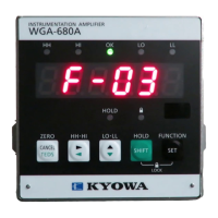
Identification of controls and indicators on the rear panel.

1-3. BCD Output Specifications

Technical specifications for BCD data output.

BCD Output - Connections and Signals

1-4. Pin and Signal Assignments

Detailed pinout and signal descriptions for BCD output.

1-5. To Connect BCD Output

Instructions for connecting external devices to the BCD output.

1-6. To Connect BCD Control Input

Instructions for connecting control input signals for BCD.

BCD Output - Settings and Timing

1-7. To Set BCD Output

Configuration options for BCD output logic and timing.

1-8. BCD Signal Timing

Timing diagrams and explanations for BCD data signals.

RS-232C Communication - Overview

2-1-1. Outline of Product

Overview of the RS-232C communication option.

2-1-2. Controls and Indicators (Rear Panel)

Identification of controls and indicators for RS-232C.

RS-232C Communication - Details

2-1-3. RS-232C Specifications

Technical specifications for RS-232C communication.

2-1-4. Pin and Signal Assignments

Pinout and signal details for RS-232C interface.

2-1-5. To Connect External Devices

How to connect external devices via RS-232C.

RS-485 Communication - Overview

2-2-1. Outline of Product

Overview of the RS-485 communication option.

2-2-2. Controls and Indicators (Rear Panel)

Identification of controls and indicators for RS-485.

RS-485 Communication - Details

2-2-3. RS-485 Specifications

Technical specifications for RS-485 communication.

2-2-4. Pin and Signal Assignments

Pinout and signal details for RS-485 interface.

2-2-5. To Connect External Devices

How to connect external devices via RS-485.

RS Communication Settings and Procedures

2-3. To Set RS-232C and RS-485

Configuration settings for RS-232C and RS-485 communication.

2-4. Communication Procedures

Steps for establishing and managing communication.

Control Commands - Outline

2-5. Outline of Control Commands

Introduction to the format and types of control commands.

Control Commands - List

2-6. List of Control Commands

A comprehensive list of available control commands.

Control Commands - Initial Settings

2-7-1. Initial settings

Detailed explanation of initial setting commands.

Control Commands - RS Line Test and System Info

2-7-1. Initial settings (cont.)

Further details on initial settings and system information commands.

Control Commands - Reading Values

2-7-2. Reading

Commands for reading indicated values and statuses.

Control Commands - Reading Original Values

2-7-2. Reading (cont.)

Command to read original values and statuses.

Control Commands - Reading Pre-set Values

2-7-2. Reading (cont.)

Command to read pre-set values for various configurations.

Control Commands - Executing Functions

2-7-3. Executing

Commands for executing self-checks, hold, and reset functions.

Control Commands - Settings (Calibrations)

2-7-4. Settings

Commands for executing calibrations and registering values.

Control Commands - Settings (Sensitivity & Smoothing)

2-7-4. Settings (cont.)

Commands for sensitivity and smoothing function settings.

Control Commands - Settings (Additional Values & Zero Comp.)

2-7-4. Settings (cont.)

Commands for setting additional values and automatic zero compensation.

Control Commands - Settings (Bridge Excitation & Level Test)

2-7-4. Settings (cont.)

Commands for bridge excitation voltage and level test settings.

Control Commands - Settings (Analog Output & Hold Modes)

2-7-4. Settings (cont.)

Commands for analog output scaling and hold modes.

Control Commands - Settings (Comparator Values & Hysteresis)

2-7-4. Settings (cont.)

Commands for setting comparator values and hysteresis.

Control Commands - Settings (Comparator Functions)

2-7-4. Settings (cont.)

Commands for setting comparator functions and limits.

Control Commands - Others and Error Handling

2-7-5. Others

Handling undefined commands and communication errors.

2-7-6. Binary code (RS-485 only)

Procedures for establishing communication and opening communication in binary.

TEDS Function - Overview and Specifications

3-1. Outline of Product

Overview of TEDS compatibility and transducer connection.

3-2. TEDS Specification

Specifications for applicable transducers and interface.

TEDS Function - Operation and Data Registration

3-3. To Connect

Instructions for connecting TEDS signals from transducers.

3-4. To Operate

Methods for operating TEDS sensitivity registration.

3-5. TEDS Data Sensitivity Registration

Process for registering TEDS data and obtaining calibration coefficients.

TEDS Function - Setting TEDS Parameters

3-6. To Set TEDS

Configuration options for TEDS reading and digital zero functions.

Trouble Shooting

Trouble and Countermeasures

Table of common issues, their causes, and recommended solutions.

Outside Drawing: WGA-680A-01 (BCD/TEDS)

Outside Drawing: WGA-680A-02 (RS-232C/TEDS)

Outside Drawing: WGA-680A-03 (RS-485/TEDS)

Outside Drawing: WGA-680A-11 (BCD/TEDS)

Outside Drawing: WGA-680A-12 (RS-232C/TEDS)

Outside Drawing: WGA-680A-13 (RS-485/TEDS)

Related product manuals