L-ACOUSTICS LA24a Manual V1.0 27/01/2003 2
8.6 DC Protection ............................................................................................................................. 20
9. MAINTENANCE............................................................................................................................... 20
9.1 Troubleshooting .......................................................................................................................... 20
10. WARRANTY.................................................................................................................................... 21
11. Technical Assistance and Service..................................................................................................... 21
LIST OF FIGURES
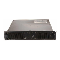
Figure 1: LA24a Front Panel .................................................................................................................... 6
Figure 2: LA24a Rear Panel ..................................................................................................................... 7
Figure 3: LA24a Rear Panel MLS Switches .............................................................................................. 8
Figure 4: XLR Input Connector Wiring ................................................................................................. 14
Figure 5: Balanced XLR wiring .............................................................................................................. 14
Figure 6: ¼” TRS plug............................................................................................................................ 14
Figure 7: LA24a Rear Panel Detail......................................................................................................... 14
Figure 8: Unbalanced Line Connection ................................................................................................. 15
Figure 9: Balanced Line with Unbalanced Equipment ........................................................................... 15
Figure 10: Loudspeaker Connection Details ......................................................................................... 15
Figure 11: Reverse polarity operation for Channel B............................................................................ 16
Figure 12: Bridged mono cabling........................................................................................................... 17
Figure 13: LA24a Front Panel Detail ..................................................................................................... 18
LIST OF TABLES
Table 1: Output Power Ratings and MLS Switch Settings for the LA24a................................................ 8
Table 2: MLS Switch Setting Applications................................................................................................ 9
Table 3: LA24a Current Draw @ 4 ohms............................................................................................. 12
Table 4: LA24a Maximum Output Power versus Mains Input Power .................................................. 12
Table 5: LA24a Output Power and Input Sensitivity versus MLS Switch Setting (32 dB gain).............. 13
Table 6: Maximum Recommended Length for Damping Factor > 20 ................................................. 16



 To Next Page