L-ACOUSTICS LA48a Manual V1.0 27/01/2003 14
6. CONNECTIONS
6.1 INPUT CONNECTIONS
6.1.1 BALANCED INPUTS
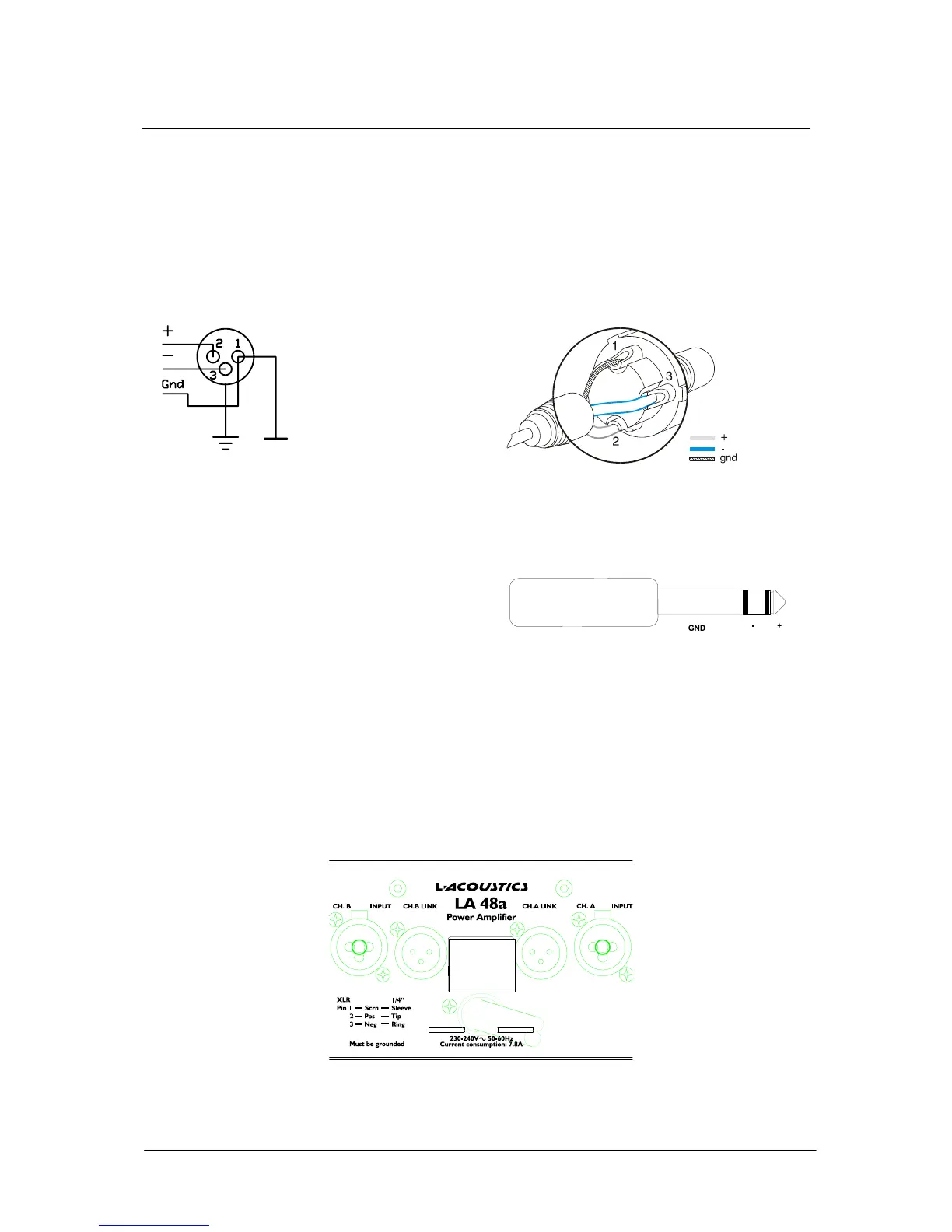
XLR Input connectors are active balanced and wired according to IEC 268 (i.e., pin 2 hot) in the
following way:
PIN 1 GROUND/SHIELD
PIN 2 HOT (+)
PIN 3 COLD (-)
Figure 4: XLR Input Connector Wiring
Figure 5: Balanced XLR wiring
The Neutrik® Combojack includes a ¼” (6.3 mm) phone jack, which is wired in parallel with the XLR
in the following manner:
TIP HOT
RING COLD
SLEEVE SHIELD/GROUND
Figure 6: ¼” TRS plug
The input impedance is high enough (20 kOhms, balanced) to allow ”daisy-chaining”, or multiple parallel
input connections. The headroom of the input circuits is also high enough to accept the maximum output
level from virtually any low-level signal source. Balanced signals are less sensitive to AC hum and radio
interference. The source impedance should be less than 1 kOhms in order to avoid high frequency loss in
long cables.
To daisy chain amplifiers, use the XLR-male connector, labeled Link, provided on each channel. This
connector is wired in parallel with the Neutrik® Combo jack on each input.
Figure 7: LA48a Rear Panel Detail
Gain=32dB



 To Next Page