LA
LALA
LA8
88
8
AMPLIFIED CONTROLLER
AMPLIFIED CONTROLLERAMPLIFIED CONTROLLER
AMPLIFIED CONTROLLER
USER MANUAL
USER MANUALUSER MANUAL
USER MANUAL
VERSION 4.0
LA8_UM_EN_4-0
w w w . l - a c o u s t i c s . c o m
24
2424
24
6.4.5 L-NET network cabling
The LA8 can be connected to a network of several controllers driven by a computer running LA NETWORK
MANAGER Software (refer to the LA NETWORK MANAGER User manual [3.4]). The connection is done using the
I/O Ethernet RJ45 sockets located on the LA8 rear panel (see Figure 8).
Connect the computer and amplified controllers to the network using straight-through Ethernet
cables of CAT5e U/FTP category (or higher) and of 100 m/328 ft maximum length.
Exception: If the Auto MDI/MDIX functionality is NOT available on a switch used to build a star or
hybrid topology, use a crossover cable between the switch and each controller.
Notes:
•
The L-NET Network is rated at 100 Mbps.
•
A straight-through cable has pin 1 of one side connected to pin 1 of the other side, pin 2 to pin 2… A crossover
cable has 1-2 and 3-6 pin pairs crossed (it can be seen directly on the cable by comparing the wire colors between
both RJ45 connectors).
•
CAT5e U/FTP stands for a category 5, unshielded cable with foiled twisted pairs. Using lower category cables or
CAT5e “patch” cables will result in connection issues.
•
The maximum length for a typical CAT5e U/FTP cable is 100m/328ft. This value is indicative and can vary
depending on the quality of the cable.
6.5 Power consumption
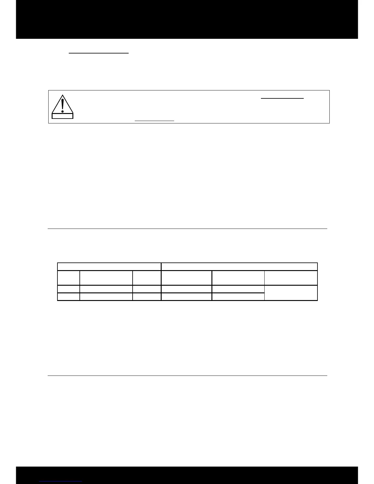
The LA8 power requirements summarized in Table 4 (4 channels being driven at the same time) are dependent of load
impedance and signal level characteristics:
Table 4: LA8 Maximum Output Power versus Mains Input Power
Maximum output power Mains input power and current draw
Load
Number of
channels
Power
1/3 Output Power
(-5 dB)
1/8 Output Power
(-9 dB)
IDLE
4 Ω 4 x 1800 W 22 A / 3100 W 11 A / 1500 W
0.4 A / 100 W
8 Ω 4 x 1100 W 15 A / 1950 W 10 A / 1300 W
The current values are given for mains rated at 230 V. Multiply by 2 for 120 V, 1.15 for 200 V, and 2.3 for 100 V.
If the voltage outsides a plus or minus 10 % range, the maximum power is no longer guaranteed.
Note: A third of the maximum output power corresponds to the worst case scenario of a program source using highly
compressed music or pink noise with amplifier driven to clip level.
An eighth of the maximum output power corresponds to a loud music program with a small dynamic range and 9 dB of
headroom (IEC standard power rating).
6.6 Heat power calculation
For example, connect a 4 Ω load to each output channel of the controller. Each output channel can now deliver up to
1800 W output power. Consider a standard use at 1/8 of full power (9 dB headroom). The power delivered per
channel is then 1800 / 8 = 225 W, leading to a total power of 4 x 225 = 900 W for the controller. According to Table 4
the controller’s power consumption is 1500 W, the heat power produced is then 1500 - 900 = 600 watts (difference
between power consumption and output power).


 To Next Page
 Loading...


