Do you have a question about the L3Harris narda PMM EP-600 and is the answer not in the manual?
Covers manual documentation, probe technology, and general introduction to the probes.
Details specifications and typical frequency response for EP-600, EP-601, EP-602, EP-603, and EP-604 probes.
Covers probe housing, connectors, battery management, accessories, and optional items.
Covers initial inspection, ambient conditions, and procedures for returning the instrument for repair.
Details safe cleaning methods and explains probe support options.
Discusses coupling effects on measurements and interaction with operator's body.
Addresses handling multiple RF sources and connecting probes via RS232 and USB.
Guides on installing probes on conical holders and tripods for accurate measurements.
Discusses factors before measuring EMF, including source characteristics and spurious signals.
Outlines requirements for probes, connections, and metering equipment for accurate measurements.
Covers basic checks, procedures, and methods to prevent measurement errors.
Details the operation of PMM EP probes and information on battery status.
Illustrates EMC applications and operation with PMM 8053B and SB10 devices.
Introduction to the EP600 CHARGER and its intended use for recharging PMM EP probes.
Details the AC adapter, power supply, and specifications of the EP600 CHARGER unit.
Identifies the components of the EP600 CHARGER unit.
Step-by-step instructions for installing PMM EP probes onto the EP600 CHARGER.
Introduction to WinEP600 software and the minimum PC hardware requirements for operation.
Step-by-step instructions for installing the WinEP600 and SetAddEP600 software on a PC.
Instructions for running WinEP600, connecting the probe, and starting the application.
Overview of the WinEP600 main window, its elements, and operational controls.
Explains how to set the frequency correction factor for precise measurements.
Details setting the reading rate and switching between XYZ and Total measurement modes.
Instructions for saving measurement data and using the plotting function for data visualization.
Guides on configuring settings, including averaging, filters, and display preferences.
Instructions for running the SetAddEP600 utility for probe configuration and management.
Describes the main window of SetAddEP600 and how to view probe data.
Procedures for uninstalling the WinEP600 software and the RS232-USB adapter driver.
Provides a disclaimer and details serial communication protocol specifications.
Explains the format and categories of communication commands for probe control.
Describes C functions for establishing communication, removing probes, and getting firmware version.
Functions for retrieving probe name, model, calibration date, battery, temperature, and serial number.
Functions for setting frequency, filters, timeouts, and reading field values.
Guides on referencing Visual Basic libraries and lists status codes for DLL functions.
Essential safety recommendations and instructions for product use and maintenance.
EC Declaration of Conformity for the EP-600 model, listing applied standards and directives.
EC Declaration of Conformity for the EP-601 model, listing applied standards and directives.
EC Declaration of Conformity for the EP-602 model, listing applied standards and directives.
EC Declaration of Conformity for the EP-603 model, listing applied standards and directives.
EC Declaration of Conformity for the EP-604 model, listing applied standards and directives.
Lists the contents of the User's Manual, including questionnaires and checklists.
Explains the technology and principles behind diode-based isotropic electric field probes.
Introduces the EP-600/601/602/603/604 probes, their technology, and key features.
Presents detailed technical specifications for the PMM EP-600 electric field probe.
Shows the typical frequency response graph for the EP-600 probe with correction OFF.
Presents detailed technical specifications for the PMM EP-601 electric field probe.
Shows the typical frequency response graph for the EP-601 probe with correction OFF.
Presents detailed technical specifications for the PMM EP-602 electric field probe.
Shows the typical frequency response graph for the EP-602 probe with correction OFF.
Presents detailed technical specifications for the PMM EP-603 electric field probe.
Shows the typical frequency response graph for the EP-603 probe with correction OFF.
Illustrates the typical anisotropy of the EP-603 probe at 50 MHz.
Details the plastic housing and optical connectors for EP-600/601/602/603 probes.
Presents detailed technical specifications for the PMM EP-604 electric field probe.
Shows the typical frequency response graph for the EP-604 probe with correction OFF.
Details the plastic housing, connectors, and axes for the EP-604 probe.
Information on the internal Li-Mn battery, charging, and discharge times.
Lists standard accessories and optional items for the PMM EP probes.
Covers initial inspection, ambient conditions, and procedures for returning the instrument for repair.
Details safe cleaning methods and explains probe support options.
Discusses coupling effects on measurements and interaction with operator's body.
Addresses handling multiple RF sources and the need for isotropic probes.
Instructions for connecting EP probes to a PC using the RS232 interface.
Provides details on RS232 connection and proper handling of fiber optic cables.
Guides for connecting EP probes to a PC using the USB interface and installing drivers.
Provides details on USB connection and proper handling of fiber optic cables.
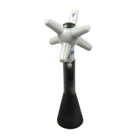
Step-by-step instructions for installing the EP probes onto the conical holder.
Illustrates the process of mounting EP probes onto the conical holder.
Instructions for correctly removing the EP probes from the conical holder.
Guides for installing EP probes onto the PMM TR-02 tripod for measurement stability.
Discusses factors before measuring EMF, including source characteristics and spurious signals.
Outlines requirements for probes, connections, and metering equipment for accurate measurements.
Covers basic checks, procedures, and methods to prevent measurement errors.
Provides guidance on preventing errors by maintaining proper distance from the sensor and objects.
Details the operation of PMM EP probes, including power-on, auto-off, and handling precautions.
Notes on connecting probes to PC, battery voltage, autonomy, and long-term storage.
Explains the use of EP probes in EMC applications for monitoring field strength.
Illustrates measurement configurations for EMC testing in open sites and TEM/GTEM cells.
Illustrates measurement configuration for EMC testing in an anechoic chamber.
Instructions for operating EP probes with the PMM 8053B meter, including display modes.
Details on using the PMM SB10 to control multiple EP probes simultaneously.
Describes the PC software for simultaneous display of field strength from multiple probes.
Introduction to the EP600 CHARGER and its intended use for recharging PMM EP probes.
Details the AC adapter, power supply, and specifications of the EP600 CHARGER unit.
Identifies the components of the EP600 CHARGER unit.
Step-by-step instructions for installing PMM EP probes onto the EP600 CHARGER.
Guides on installing probes on the charger and interpreting the LED status indicators.
Provides tables detailing the LED status for start-up and charging phases.
Introduction to WinEP600 software and the minimum PC hardware requirements for operation.
Step-by-step instructions for installing the WinEP600 and SetAddEP600 software on a PC.
Instructions for running WinEP600, connecting the probe, and starting the application.
Guidance on handling User Account Control prompts and specifying the installation folder.
Displays progress screens for the WinEP600 installation process.
Confirms successful installation and instructions for creating a desktop shortcut.
Instructions for running WinEP600, connecting the probe, and starting the application.
Guides on selecting the communication port (RS232/USB) and confirming incoming connection.
Details the main window layout and provides descriptions for various commands and controls.
Explains the title bar information and the function of window control buttons.
Describes the measurement values displayed in the main window, including units and status.
Explains how to set the frequency correction factor for precise measurements.
Details how to set the time interval between subsequent readings.
Guides on selecting XYZ or Total mode and interpreting messages for out-of-range values.
Instructions for saving measurement data to a text file.
Explains how to use the PLOT function to display measured data graphically over time.
Guides on customizing plot appearance, including resolution, scale, colors, and separators.
Details on controlling plot analysis, including play, pause, and stop functionalities.
Instructions for saving plot data in table format (TXT) for further analysis.
Guides on resuming, pausing, and terminating plot analysis and saving results.
Explains the HOLD/RUN function to freeze readings and the EXIT function to close the program.
Details on configuring digital filters to improve probe resolution and sensitivity.
Describes filter characteristics like settling time, power consumption, and sensitivity for different applications.
Guides on configuring the number of readings to calculate the arithmetic average (AVG).
Details on setting display colors for the main window and plot appearance.
Explains Minimized UI, Measurements Log function, and language selection.
Accessing probe information (firmware, serial number) and manufacturer details.
Guides for running SetAddEP600 and identifying COM ports in Device Manager.
Instructions for configuring port settings and advanced options for serial communication.
Instructions for setting the communication port (COMM=N) in the SetAddEP600 shortcut properties.
Displays the main window of SetAddEP600 and indicates connection status with the probe.
Describes the main window and title bar of the SetAddEP600 utility.
Details how to view probe data and set a new probe address in SetAddEP600.
Procedures for uninstalling the WinEP600 and SetAddEP600 software from the PC.
Instructions for uninstalling the driver for the RS232-USB adapter.
Confirms the completion of the RS232-USB adapter driver uninstallation.
Provides a disclaimer and details serial communication protocol specifications.
Explains the format and categories of communication commands for probe control.
Explains command categories, Master/Slave modes, and auto-switch-off settings.
Lists query commands for retrieving probe firmware, calibration, battery, serial number, and field data.
Details setting commands for frequency, filter, and probe power off.
Explains operative commands for entering storing mode and setting the probe address.
Describes C functions for establishing communication, removing probes, and getting firmware version.
Functions for retrieving probe name, model, calibration date, battery, temperature, and serial number.
Functions for setting frequency, filters, timeouts, and reading field values.
Functions for reading the probe's battery status and internal temperature.
Details the PMM_SerialNumber function for retrieving the probe's serial number.
Functions for setting the frequency correction factor and processing filter for measurements.
Details the PMM_SetTimeout function for configuring communication timeout.
Details the PMM_SetAutoOffTime function for setting probe auto-switch-off time.
Functions for reading total field and axis-specific field values.
Guides on referencing Visual Basic libraries and lists status codes for DLL functions.
Covers inspection of accessories and recommended ambient conditions for storage and operation.
Details the PMM 8053-OC converter for connecting fiber optics to a PC's serial port.
Describes the 8053-OC-PS power supply for the 8053-OC converter when PC power is insufficient.
Details the characteristics and features of the PMM TR-02A tripod for probe support.
Illustrates tripod leg inclination settings and probe mounting on the TR02A.
Describes the PMM 8053-SN swivel used for mounting probes on the TR-02A tripod.
Details the PMM TT-01 telescopic extension for adjusting probe distance.
Refers to the SB-10 User's Manual for the PMM SB-10 Switching Control Box.
| Brand | L3Harris |
|---|---|
| Model | narda PMM EP-600 |
| Category | Accessories |
| Language | English |