2
1.0 Equipment Handling
1.1 Storing the A31
If the A31 is to be stored for more than a few days after delivery, it should be stored within its shipping container.
The location chosen for storage should be within an ambient temperature of -40 to 140°F (-40 to 60°C) with a
non-condensing relative humidity of 0 to 95%. Storage should not exceed 2 years due to the limited shelf life of
the DC filtering capacitors when they are not in service.
1.2 Moving the A31
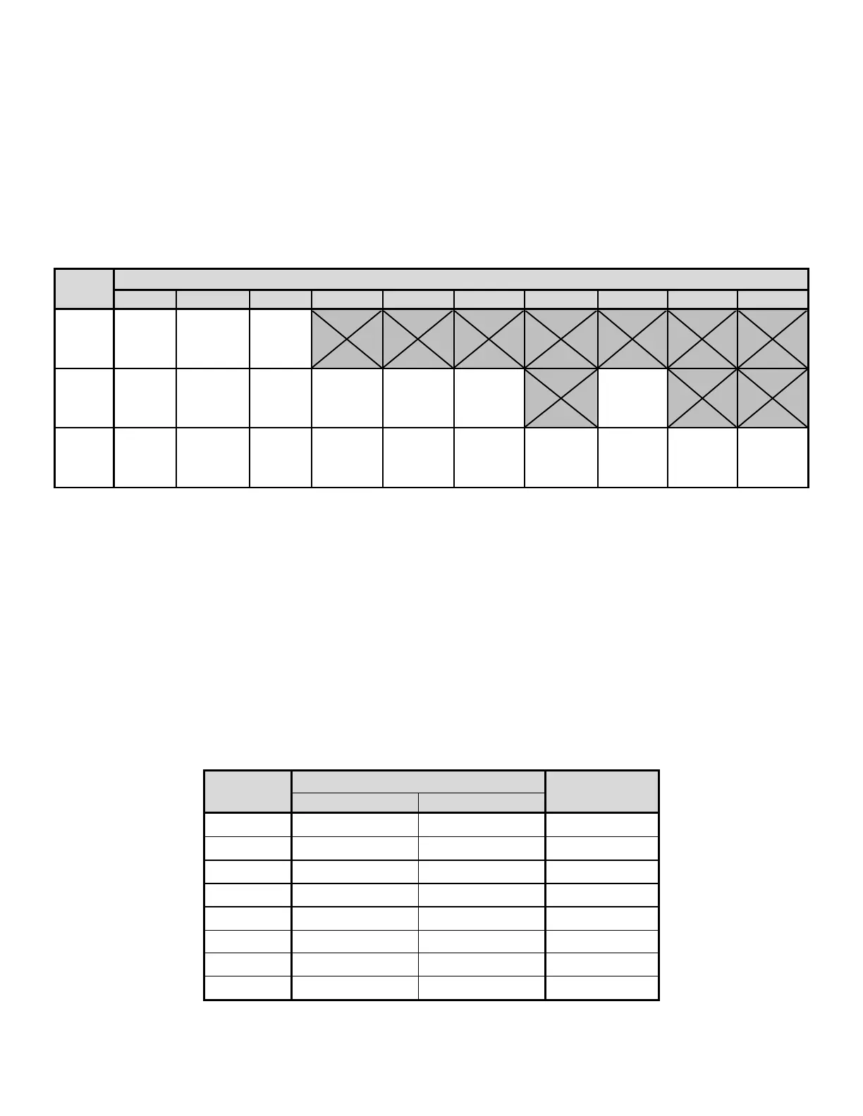
After careful inspection and upon verification that the A31 is undamaged, identify the enclosure style and weight
of the A31 inverter. Refer to the table below:
Table 1 – Case Type and Weight Table
2.0 Installation
2.1 Mounting the A31
When mounting the A31 in any configuration, consider the size and weight of the inverter. The rack and/or floor
must be able to support the weight of the inverter, as well as an additional safety factor. Refer to data sheet to
verify the weight of the inverter and the method of mounting using the table below. The location chosen for the
inverter should be within an ambient temperature range of 32˚F to 122˚F (0˚C to 50˚C) with a non-condensing
relative humidity no higher than 95%. The inverter should be mounted in an area free of explosive materials and
away from any liquids. The A31 utilizes convection cooling so a clearance of at least 6 in (152 mm) of free air
must be maintained on the top, bottom, left and right side for cooling air. Maintain 36 in (914 mm) or more of
clearance at the front of the inverter in order to allow for operation and maintenance. The bolts or screws used
to secure the inverter should be sufficient length to assure a vibration-free mounting. The preferred fastener is a
machine bolt backed with a flat washer, lock washer, and nut. All hardware should be corrosion resistant.