SCADA INTERFACE INSTRUCTIONS - OPTION 21Q - FOR A36D/TPSD SYSTEMS/341S
Page 7 of 10
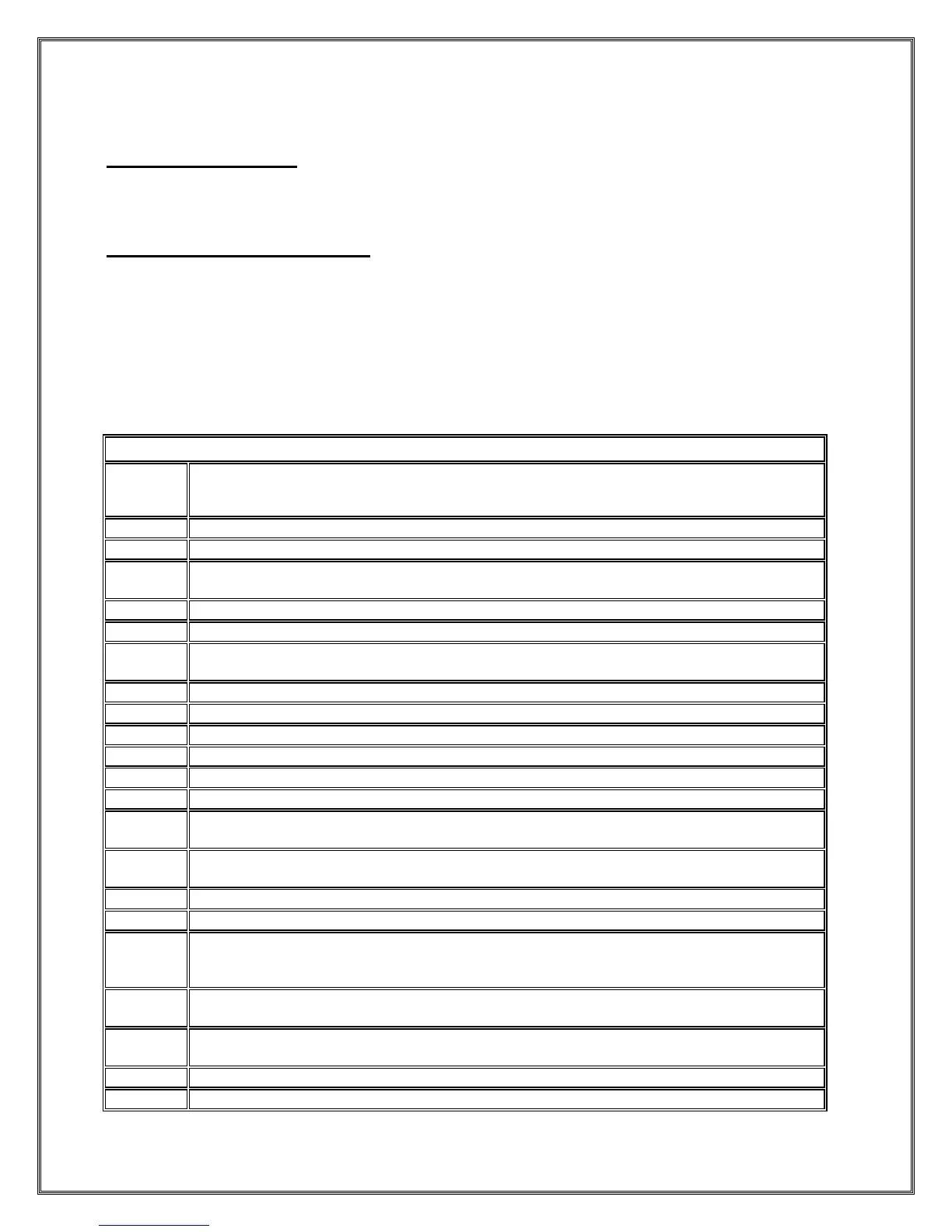
LaMarche Modbus Implementation
Supported Modbus Types
RTU
TCP
Supported Modbus Function Codes
01 – Read Coil Status (0X)
02 – Read Discrete Input Registers (1X)
03 – Read Holding Registers (4X)
04 – Read Input Registers (3X)
05 – Write Single Coil
06 – Write Single Register
10 – Write Multiple Coils
0F – Write Multiple Registers
Float/EQ Mode Indicator (FLOAT=0, EQUALIZE=1)
Temperature Compensation Enable (ENABLED=1).
LCD Backlight Timeout Enable (ENABLED=1)
This has no effect on Chargers equipped with VFD Displays.
Include Low Current Alarm in Summary Alarm (INCLUDED=1)
Include AC Alarm in Summary Alarm (INCLUDED=1)
Include Ground Detection Alarms in Summary Alarm (INCLUDED=1). TPSD ONLY.
For A36D this point will always read 0 and writes to are prohibited.
Include Over Temperature Alarm in Summary (INCLUDED=1)
Latch Summary Alarm (YES=1)
Latch AC Fail Alarm (YES=1)
Latch Low Voltage Alarm (YES=1)
Latch High Voltage Alarm (YES=1)
Latch High Voltage Shutdown Alarm (YES=1)
Latch Positive Ground Alarm (YES=1). TPSD ONLY.
For A36D this point will always read 0 and writes to are prohibited.
Latch Negative Ground Alarm (YES=1). TPSD ONLY.
For A36D this point will always read 0 and writes to are prohibited.
Latch Overload Alarm (YES=1)
Latch End of Discharge Alarm (YES=1)
Reset Alarms (YES=1)
Write a “1” to reset alarms. After alarms are reset software in the controller sets this
point to “0”.
Ground Detection Alarm Enable. (ENABLED=1, DISABLED=0) TPSD ONLY.
For A36D this point will always read 0 and writes to are prohibited.
Test All Alarm Contacts (BEGIN TEST=1, END TEST=0). Note the HVSD alarm contacts
are not tested remotely.
Test Negative Ground Contacts (BEGIN TEST=1, END TEST=0). TPSD ONLY.
Test High Voltage Alarm Contacts (BEGIN TEST=1, END TEST=0).
 Loading...