5
this criterion.
4.8 FORCED ROT
ATION. During the normal operation, demand variations cause pressure
huntings out of the dead zone, therefore the control algorithm applied with par.20=YES
induces an automatic swap of the running compressors and, as a final result, a total run time
equalization.
If, on the contrary, the pressure remains within the dead zone for a long period, no output
variation will take place. A remedy is to enable forced rotation.
By giving par.12 a value greater than 0, if the COPS finds a running compressor achieving
the time lapse programmed (ex. 60 min.) and a stopped compressor fulfilling the swapping
criteria (shorter total run time, minimum stop etc.), then it forces rotation process. The
controller switches off the compressor to get the designated one running.
4.9 OUTPUT OPTIMIZA
TION. If two compressors are simultaneously reduced in capacity (one or
more stages switched off) as a result of an alarm (output diagnostics, down scaling etc.), the
COPS starts the optimization function. It proceeds to a progressive power shift from a
compressor to the other, according to the programmed control algorithm.
This optimizes the electrical power consumption without changing the mechanical power.
4.10 POWER SCALING
. If alarms with down scaling function are detected, the number of
switched on outputs is progressively reduced in 5 sec steps, until reaching par.16. For
example, if the COPS receives a High Pressure signal from the condenser while operating
with 6 switched on outputs and par.16=3, a progressive quick down scaling of the number
of outputs will take place until, in 10 sec, 3 outputs only remain on.
During off switching the programmed control sequence is maintained.
When the COPS operates in down scaling, the number of on outputs may only be further
reduced and not increased. In addition, the OPTIMIZATION and FORCED ROTATION
functions are suspended.
5. ANOMALIES AND ALARMS
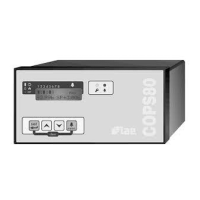
The COPS 80 features a sophisticated abnormal operation condition detection system. When an
anomaly is detected, area [8] of the display shows its source (see 2.3) and, as long as the condition
persists, the alarm relay contacts will change status and LED [3] blinks. The buzzer goes off
simultaneously with the other signallings but it can be muted by pressing any of the keys.
Every alarm event is stored in non-volatile memory, it will not therefore be lost with a power failure.
For this function 10 records are available and when they are filled the following alarms will be lost.
Therefore we recommend to periodically erase the old alarms from the memory as described in 2.5.
On war
ming-up and stand-by all alarms are suspended
.
In the next paragraphs is a description of the alarm sources, the corresponding indications on area
[8] of the display and the possible repercussions on the control logic.
5.1 TRANSMITTER F
AULT/OVERRANGE
, "probe". Signalled if the pressure transmitter exceeds
the range programmed with par.24 (with 4...20mA exclusively) or par.25.
5.2 RELA
TIVE HIGH PRESSURE ON SUCTION, "rel.HP". Signalled if the suction pressure
continuously remains beyond the dead zone upper limit (see 4.3) for a time longer than
par.8. The alarm ends when pressure goes back within the dead zone.
5.3 HIGH PRESSURE ON CONDENSER SIDE
, "psw.HP". Signalled when par.35=YES and the
relevant input does not receive the required on voltage. This alarm causes output down
scaling (see 4.10). The alarm ends when the input receives the required on voltage again.
With par.35=NO this alarm is inhibited.
5.4 LOW PRESSURE ON SUCTION
, "psw.LP". Signalled when par.36=YES and the relevant
input does not receive the required on voltage. This alarm causes output down scaling (see
4.10). The alarm ends when the input receives the required on voltage again.
With par.36=NO this alarm is inhibited.
5.5 LOW REFRIGERANT LIQUID
, "level". Signalled when par.37=YES and the relevant input
does not receive the required on voltage for a period longer than par.39. The alarm ends
when the input receives the required on voltage again.
With par.37=NO, this alarm is inhibited.
5.6 AUXILIAR
Y ALARM, "aux.". This alarm is available for installers' general purposes. It signals
when one or more external alarm events occur, provided that par.38=YES and the relevant
input does not receive the required on voltage. The alarm ends when the input receives the
required on voltage again.
With par.38=NO, this alarm is inhibited.
5.7 OUTPUT F
AULT, "out 'N'". Usually every large or middle sized motor compressor has got a
series of protecting devices aiming at preserving itself from damage arising from winding
overheating, phase interruption, lubricant lack etc. By linking all these contacts together, a
safety chain is created that opens whenever a critical condition occurs.
The output monitoring has the purpose of detecting contactor coil supply interruption as a
result of protection intervention (see figure 3).
The monitoring is enabled by giving YES to the relevant flag (par.27...34). If the diagnostics
is enabled and its feedback input does not receive the required on voltage, the COPS detects
the anomaly and reacts in different ways depending on the load connected, compressor or
stage.
Compressor anomaly: it signals the alarm condition (out'N’'' and (!) on display; LED [3];
relay etc.) switches off all stages to allow a following soft start; keeps that output on to detect
a possible self-recovery.
A compr
essor in alarm mode is excluded from the on and off switching sequences.
 Loading...
