We thank you for choosing an LAE controller. Before proceeding to the installation of the RDC 12, please read this instructions sheet carefully;
only in this way you will obtain maximum performances and safety.
1. INSTALLATION
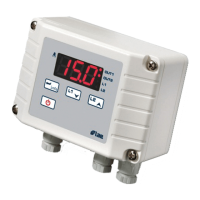
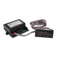
1.1 The instrument has got a size of 77x35x97 mm (WxHxD). It’s inserted into the panel through a 71x29 mm hole and secured via the suitable
brackets exerting corret strength. The rubber gasket must be placed between the panel and the instrument front, so please make sure that there are
no gaps allowing liquid infiltrations.
1.2 The unit works with an ambient temperature between -10°...+50°C and 15%...80% relative Humidity. To reduce the effects of electro-magnetic
interference, place the cables carrying signals (probes and serial connections) and the controller as away as possible from power lines.
1.3 Probes, power supply and outputs/inputs must be wired strictly following the diagram indicated on the enclosure, where the maximum loads also
appear. For supply voltage, the suitable transformer (mod. TRxxx) must be used.
1.4 Probe T1 measures air temperature and is used for the thermostat function; probe T2 measures the evaporator temperature and must be secured
to it in the place where the maximum frost growth occurs. Probe T3 is for measuring and displaying product temperature and is used for the night
thermostat. It must therefore be located in the position indicated by the manufacturer of the refrigerator -typically in the return air-.
1.5 The RS485 serial communication or TTL output for the remote display is available on the DATA connector. PIN 1 is identified by a dot.
Caution: • If the relays switch a large load frequently, we suggest you contact us to obtain information about the relay contact life.
•Where delicate or valuable products have to be maintained under strict conditions, please use a different controller for limit and alarm functions.
2. CONTROL PARAMETERS
The adaptation of the RDC 12 to the the system that it controls is achieved through the parameters in the SETUP. Access to the parameters is obtained
by pressing + + for 4 seconds. Scroll through the parameters by pressing or until you select the desired one. Check its value by means
of and change it via + or . Exit from the SETUP occurs after 10 sec. of no key activation. To help yourself during programming, refer to the
table annexed.
3. DISPLAYS
3.1 D
URING ORDINARY
C
ONTROL
. At the power up, the display shows "---" for 5 sec. during which the unit carries out a self-check; then the temperature
T3 appears. In some cases, owing to the structure of the cabinet or air stratification, the probes can not measure the desired temperature. If necessary,
through the parameters oS1, oS2 and oS3 the temperatures t1, t2 and t3 measured by the probes can be adjusted in order to obtain the desired
values for computing: thermostat T1=t1+oS1; defrost T2=t2+oS2; display T3=t3+oS3.
Through the SiM parameter it’s possible to reduce the fluctuations of the displayed temperature by simulating the behaviour of product core
SPL minimum programmable temperature [-50 ... +150°]
SPh maximum programmable temperature [SPL ... +150°]
hyS thermostat on switching hysteresis [+01 ... +20°K]
coF cooler minimum off time [00 ... 10 minutes]
con cooler minimum on time [00 ... 10 minutes]
cdc cooler safety run in case of probe failure [00=off ... 10(0)%=always on]
crS cooler re-start delay after power failure [00 ... 120 seconds]
dLi defrost limit temperature [+01 ... +70°]
dto defrost time out [01 ... 120 minutes]
drP drain time [00 ... 10 minutes]
diS display control during defrost [-01=”dEF”; 00=”T3”; 1... 30 minutes=timed “dEF”]
dty defrost type [Fan=off cycle; ELE=electrical; GAS=hot gas]
Fct evaporator fan control [-01=always on; 00=on/off with cooler; 1... 10 minutes=delayed off]
FrS fan re-start after defrost [-50 ... +150°]
Fid ventilation during defrost [00=off; 01=T2<FrS; 02=always on]
Alo low alarm threshold [-50 ... +150°]
Ahi high alarm threshold [ALo ... +150°]
AdL temperature alarm delay [-01=excluded; 00... 120 minutes]
Ain alarm input selection [probe 1, 2, 3]
oS1 thermostat probe offset [-20 ... +20°K]
oS2 evaporator probe offset [-20 ... +20°K]
oS3 displayed probe offset [-20 ... +20°K]
SiM slowdown of displayed temperature [00 ... 200]
Adr peripheral number [00 ... 255]
INSTRUCTIONS FOR INSTALLATION AND USE.
RDC123T1R3C
RDC123T1R3J