Do you have a question about the LAE electronic COPS 80 and is the answer not in the manual?
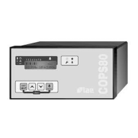
Fasten the COPS 80 main unit to a panel using its snap-on system.
Secure COPM 28 control modules to the DIN-rail, close to the main unit.
Ensure the system operates between -10°...+50°C and 15%.. 80% relative humidity.
Route signal cables away from power wires and fold excess cable to reduce interference.
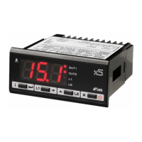
Initial display shows software release, then specific function areas.
Area [7] displays enabled outputs (1-8) and their operational status.
Area [8] indicates the source of active alarms (e.g., probe, pressure).
Area [8] shows the number of stored alarms when no active alarms are present.
Scroll through stored alarms using keys [6]+[5]; clear with [6]+[4].
LED [2] illuminates when compressors reach programmed maintenance hours.
LED [3] blinks to indicate detected internal or external alarms.
Access programming by holding key [4] and entering the pass code.
Use keys [5] to select parameters and [4]+[5] to set values.
Programming exits automatically after 15s of inactivity or by pressing both keys [5].
Control functions are suspended; outputs progressively switch off.
Outputs remain off for a programmed duration on power-up.
Maintains suction pressure around the reference value by controlling outputs.
Waits for stable conditions before switching an output on.
Waits for stable conditions before switching an output off.
Determines switching order based on rotation or fixed sequence.
Limits compressor starts per hour to prevent short cycling.
Automatically swaps running compressors for balanced run time.
Progressive power shift between compressors for electrical efficiency.
Reduces switched-on outputs during alarms with down scaling function.
Alarm triggered if pressure transmitter exceeds programmed range.
Alarm if suction pressure stays high beyond the dead zone for a set time.
Alarm triggered by the condenser high pressure switch input.
Alarm triggered by the suction low pressure switch input.
Alarm if liquid level input is inactive for a specified delay.
Signals general external alarm events via a dedicated input.
Detects anomalies in compressor output monitoring or protection devices.
Handles stage anomalies and power supply failures with specific alarm signals.
Allows changing the display language via parameter 3.
Adjust LCD contrast for optimal readability using parameter 4.
Select refrigerant media for accurate pressure-temperature conversion.
Correct transmitter reading via parameter 22 or recalibrate.
Configure periodical maintenance warnings using parameters 40-48.
| Brand | LAE electronic |
|---|---|
| Model | COPS 80 |
| Category | Controller |
| Language | English |