2
Before proceeding to the installation of the COPS 80, we recommend you to read this instruction
booklet carefully and entirely. Only in this way you will obtain maximum performance and reliability.
The COPS 80 controls the suction pressure on multi-compressor packs for variable demand
cryogenic plants. Through sophisticated algorithms the COPS 80 can control up to eight outputs to
drive single or multiple stage compressors and monitor the correct function of the whole plant on real
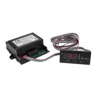
time. The main unit is connected by means of ribbon cable to one or two COPM 28 modules in
which are the outputs and their diagnostics.
1 INSTALLATION
1.1 Secure the COPS 80 main unit through its snap-on system to a 0.7...1.5mm thickness panel,
with 182x81 mm cutout. Carefully check that there is no gap between the rubber gasket and
the panel.
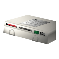
1.2 Secure the COPM 28 control modules to the DIN-rail, as close as possible to the main unit.
1.3 For a correct function, the system must operate at an ambient temperature between
-10°...+50°C and 15%.. 80% relative humidity.
To reduce the effects of electro-magnetic disturbances, locate the signal cables (probe, ribbon
cables etc.) and the controller as away as possible from contactors and power wires. Do not
wrap the excess of cable but "Z" fold it.
1.4 Probe, power supplies and all inputs/outputs of the system must be connected strictly
following the indications appearing on the technical sheet (see fig. 2 and 3).
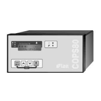
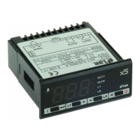
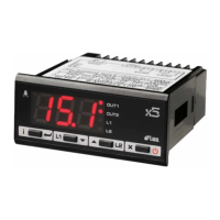
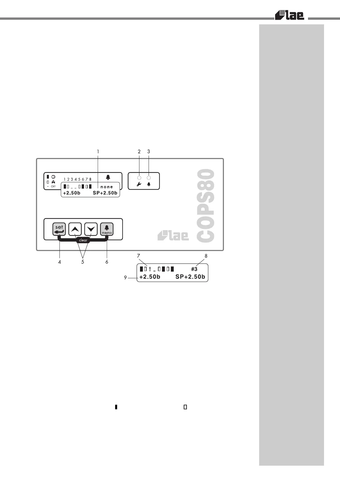
FIGURE 1
1 Backlit LCD display 6 Key to display stored alarms
2 Periodic maintenance LED 7 Output status indicator
3 Current alarm LED 8 Alarm status/counter indicator
4 Programming access key 9 Operating data
5 Increase/decrease keys
CAUTION!: The wiring panel of the COPS 80 is under voltage. Beware of electrical shocks; an
accidental contact may be fatal to persons or animals.
2 INDICATIONS
The LCD [1] allows to clearly display all possible indications helping to understand number and
configuration of the compressors, their present status and the accumulated run time, pressure or
temperature of the gas in the suction manifold, possible current or stored alarms.
To facilitate understanding even more, it's possible to select the language (English, German, Spanish,
Italian).
2.1 On power-up, the entire display [1] is on for 2 seconds approx., after that the software
release appears and finally all display areas take their specific functions.
2.2 In area [7] of the display the enabled outputs, from 1 to 8, and their status appear: stand-
by, control output off status for an undefined time; nnnn, time left to the end of the warming-
up phase; (-) switched off output; ( ) switched on compressor; ( ) switched on stage; (!)
output on alarm from diagnostics input.
2.3 If alarms are on, on area [8] their source appears: probe, pressure transmitter fault or
overrange; out'N', no feedback from output 'N'; rel.HP, pressure exceeding the high dead
zone; psw.HP, HIGH Pressure switch external contact; psw.LP, LOW Pressure switch
external contact; level, refrigerant liquid external contact; aux., auxiliary alarm contact
opening.
Area [8], if no alarms are on, shows the number of stored alarms: none, 1,..10.
2.4 In area [9], through keys [5] it's possible to select the data to display: suction GAUGE
pressure and setpoint; corresponding temperature and setpoint; totalized run time of the