Thank you for having chosen an LAE electronic product. Before installing the instrument, please read this instruction booklet carefully
in order to ensure safe installation and optimum performance.
1. INSTALLATION
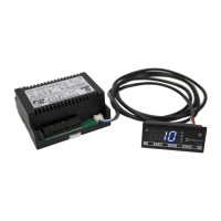
1.1 The LCD15, size 77x35x77 mm (WxHxD), is inserted into the panel through a hole measuring 71x29 mm and is fixed by
means of the suitable clips, by pressing gently. If fitted, check that the rubber gasket adheres to the panel perfectly, in order to prevent
debris and moisture infiltration to the back of the instrument.
1.2 The instrument should work with room temperatures between -10°.. +50°C and relative humidity between 15%.. 80% inclusive.
Supply voltage, switched powers and connection set-up should scrupulously comply with the indications given on the container. To
reduce the effects of electromagnetic disturbance, keep the sensor and signal cables well separate from the power wires.
1.3 The sensor T1 measures the air temperature and activates in the thermostat control cycle; it should be placed inside the
appliance in a point that truly represents the temperature of the stored product. The sensor T2 measures the evaporator temperature
and should be placed where there is the maximum formation of frost. If fitted, sensor T3 should be located between the condenser
fins, close to the condenser outlet.
CAUTION: should the relays have to switch a heavy load frequently, it is advisable to contact the manufacturer for indications on the lifetime of
the contacts.
Whenever products must be kept within very severe specifications or the products have considerable value, the use of a second instrument is
recommended, which activates upon or warns of any malfunction.
2. OPERATING MODES
Upon switching on, just the central line (autotest) appears on the display for approximately three seconds and the subsequent indications depend
on the operating status of the controller. TABLE 1 gives the indications associated with the various states, whereas the symbols appearing below
are explained in TABLE 2.
2.1 STANDBY. If button is pressed for 3 seconds, it allows the LCD15 to be put on a standby, or to resume output control (with
parameter SB=YES only). An indication on the display shows that the outputs are off permanently.
2.2 N
ORMAL. During normal operation, the display shows the temperature measured by probe T1, presented in the most appropriate
manner. Parameter SCL may be adjusted in °C with auto-range (SCL=1°C), in °C with 1° fixed resolution (SCL=2°C) or in Fahrenheit
(SCL=°F). The measured temperature may be corrected with a fixed offset by assigning a value other than 0 to the parameter OS1.
Additionally, prior to display, the temperature is treated by an algorithm that allows the simulation of a thermal mass directly