EasyManua.ls Logo

LAE LDU15 User Manual

LAE LDU15
4 pages
To Next Page IconTo Next Page
Page #1 background imageLoading...
Page #1 background image
Thank you for having chosen an LAE electronic product. Before installing the instrument, please read this instruction booklet carefully in order to
ensure maximum performance and safety.
1. INSTALLATION
1.1 The LDU15, size 77x35x77 mm (WxHxD), is inserted into the panel through a hole measuring 71x29 mm and is fixed by
pressing gently into the relative clamps. The rubber gasket should be inserted between the instrument frame and the panel, checking
that it adheres perfectly in order to prevent infiltration.
1.2 The instrument should work with room temperatures between -10°.. +50°C and relative humidity between 15%.. 80% inclusive.
Supply voltage, switched powers and connection set-up should scrupulously comply with the indications given on the container. To
reduce the effects of electromagnetic disturbance, keep the sensor and signal cables well separate from the power wires.
1.3 The sensor T1 measures the air temperature and activates in the thermostat control cycle; it should be placed inside the appliance
in a point that truly represents the temperature of the stored product.
CAUTION: should the relays have to changeover a heavy load frequently, it is advisable to contact the manufacturer for indications on the lifetime
of the contacts.
Whenever products must be kept within very severe specifications or the products have considerable value, the use of a second instrument is
recommended, which activates upon or warns of any malfunction.
2. CONFIGURATION
The controller or regulator is adapted to the controlled system by suitably programming the configuration parameters, that is, through
the setup. The setup is accessed by pressing the buttons + + in succession and keeping them pressed simultaneously for 3
seconds. The available parameters appear in table 1 as shown below.
Press the button to pass from one parameter to the next and the button to go back. Press to display the value correlated to
the parameter and press and or simultaneously to change it. Exit from setup is by pressing or is automatic after 30 seconds
of not using the keypad. Setpoint SP display and adjustment is also possible during normal operation of the controller by pressing the
and or buttons. The range in any case remains within the limits SPL and SPH.
3. DISPLAYS
Upon switching on, just the central line (autotest) appears on the display for approximately three seconds and the subsequent
indications depend on the operating status of the controller. Table 2 gives the indications associated with the various states.
The temperature measured by the sensor T1 is handled by the microprocessor so that it is displayed in the most representative way. In
other words, the parameter SCL is used to select the display in °C with 0.1/1° auto-range (SCL=1°C), in °C with 1° fixed resolution
SET
A
UX
SET
SET
SET
INSTRUCTIONS FOR INSTALLATION AND USE.
LDU15
SPL -10.0.. SPH [°] Minimum temperature set point
SPH SPL.. +25.0 [°] Maximum temperature set point
SP SPL.. SPH [°] Effective temperature set point
HYS +0.1.. +10.0 [°] Thermostat hysteresis
CRT 0.. 30 [min] Compressor rest time
CDC 0.. 10 Compressor regulation with sensor T1 failure
DFR 0.. 24 Defrosting frequency /24h
DTO 1.. 120 [min] Defrosting duration
DDY 1.. 60 [min] Defrosting display control
ATL -12.0.. 0 [°] Low alarm differential
ATH 0.. +12.0 [°] High alarm differential
ATD 0.. 120 [min] Temperature alarm delay
ACC 0.. 52 [weeks] Condenser periodic cleaning
OAU NON/SBY/MAN/DEF/ALR Auxiliary output mode of operation
BAU NON/SBY/MAN Auxiliary button mode of operation
SCL 1°C/2°C/°F Readout scale
OS1 -12.5.. +12.5 [°] Sensor T1 correction
SIM 0.. 100 Display slowdown
ADR 1.. 255 Peripheral address
TABLE 1
Question and Answer IconNeed help?

Do you have a question about the LAE LDU15 and is the answer not in the manual?

LAE LDU15 Specifications

General IconGeneral
OutputRelay
Operating temperature-10 to 60 °C
DisplayLED
Power supply24V DC
Input Voltage24V DC
Weight150g

Summary

Installation and Mounting

LDU15 Panel Mounting and Gasket

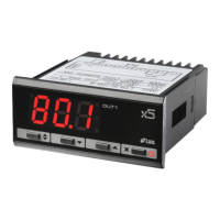
Details LDU15 dimensions, panel hole size, mounting method, and rubber gasket placement for infiltration prevention.

Operating Environment and Electrical Safety

Specifies operating temperature/humidity ranges, compliance with supply voltage, and cable separation for EMC.

Sensor Placement and Load Considerations

Guides T1 sensor placement for accurate temperature measurement and advises on heavy load relay usage and dual instrument recommendation.

Configuration Setup

Accessing and Navigating Configuration

Explains how to enter, navigate, and modify configuration parameters using button sequences and the setup menu.

Parameter Overview and Adjustment

Lists key configuration parameters like SPL, SPH, SP, HYS, and explains how to adjust them.

Display Indications

Display Status and Temperature Formatting

Describes initial display states, subsequent indications based on controller status, and temperature display formatting.

Display Codes and Meanings

Details the meaning of display codes such as DF, HI, LO, E1, and CLN during operation.

Thermostat Control

Thermostat Operation Logic

Explains thermostat control based on temperature, set point, hysteresis, and compressor rest time.

Sensor T1 Failure Handling

Describes how the output is controlled for a fixed time if sensor T1 fails, using the CDC parameter.

Defrosting Function

Automatic and Manual Defrosting

Details how defrosting starts automatically based on DFR or manually using buttons.

Defrosting Activation and Display

Explains defrosting activation, display of 'F', and related timing parameters DTO and DDY.

Alarms and Warnings

Temperature Alarm Thresholds

Defines ATL and ATH parameters for setting temperature alarm thresholds below and above set point.

Alarm Delay and Bypass

Explains the ATD parameter for alarm delay and how high-temperature alarms are bypassed during defrosting.

Condenser Cleaning Indication

Describes how the ACC parameter enables periodic condenser cleaning reminders.

Auxiliary Functions

Auxiliary Output and Button Control

Explains how OAU and BAU parameters control auxiliary relay functions and button actions.

Auxiliary Function Examples

Provides examples of OAU and BAU parameter combinations for various auxiliary functions like MAN, SBY, and ALR.

Connectivity and Warranty

PC Connection and Address Setting

Details the serial port for PC connection and the importance of setting unique ADR values for peripheral address.

Product Warranty Information

Outlines the one-year warranty for defects due to materials or workmanship and limitations.

Wiring Diagrams

LDU15 Wiring Configuration

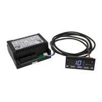
Illustrates the wiring connections for the LDU15 instrument, showing sensor, auxiliary, and power terminals.

Related product manuals