14
P/N 471243 Rev. D 1-19-00
Installation (contd.)
WATER CONNECTIONS
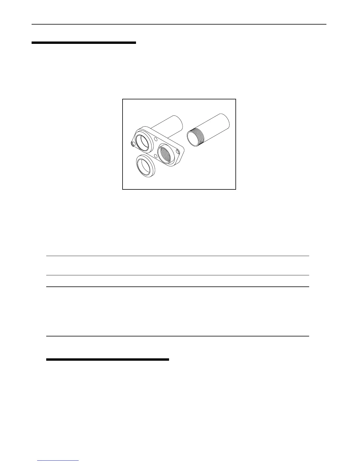
QUICK-FLANGE II INSTALLATION INSTRUCTIONS
Figure 12.
FOR 1½ SCHEDULE 40 CPVC or ABS PIPE or SCHEDULE 80 PVC
(you may adapt to SCH 40 PVC 12 inches beyond the Quick Flange II)
(1½ in. npt x 1½ in. CPVC/ABS slip male adaptor may be required )
1. Insert 2 in. rubber gaskets over 2 in. gasket retainer rings molded to bottom of Quick-Flange II;
see Figure 12.
2. Bolt Quick-Flange II to header using supplied 3/8 in. bolts and 3/8 in. washers.
3. Using pipe dope, thread pipe directly to Quick-Flange II.
a. Or, first thread a 1½ in. npt x 1½ in. slip CPVC/ABS male adaptor (not supplied) to the
Quick-Flange II ,and after preparing the joint by sanding with a medium grit sandpaper, glue
the pipe to the adaptor with a quality solvent glue.
NOTE
ALL VERSIONS OF THE LAGUNA 100K INCLUDE A QUICK-FLANGE II ADAPTOR
Each Laguna 100K Quick-Flange II Accessory Kit, p/n 471083,
contains the following items:
One (1) Quick-Flange II unit
Two (2) 2 in. Rubber Gaskets
Four (4) 3/8 in. Bolts
Four (4) 3/8 in. Washers
PRESSURE RELIEF VALVES
Where local, (or Canadian), codes require the use of a Pressure Relief Valve (PRV), the PRV may
be installed in a tee fitting placed as close as possible to the heater water outlet with no intervening
valves between the PRV and the heater.


 To Next Page