An asterisk alongside a lighting effect indicates that there may be options in the way that it can be set up so
there are additional specific detailed instructions and explanations available for that particular light effect.
Changing which controller button acts on or activates each function:
This is often called “function mapping” but that’s a little geeky so we prefer to call it “function allocation”
In cheaper Decoders you have no choice, however all of our LaisDcc Decoder functions are able to be
re-
allocated to operate with a wide variety of function buttons, adding far more flexibility of use and giving you
full
control of how you operate.
To do this each function has been allocated one or two CVs that, depending on the number entered, will
control which of your DCC systems function buttons it will react to.
We do strongly recommend you confirm how many functions your controller can operate and keep all
functions allocated to buttons which allow “one push access” for easy operation.
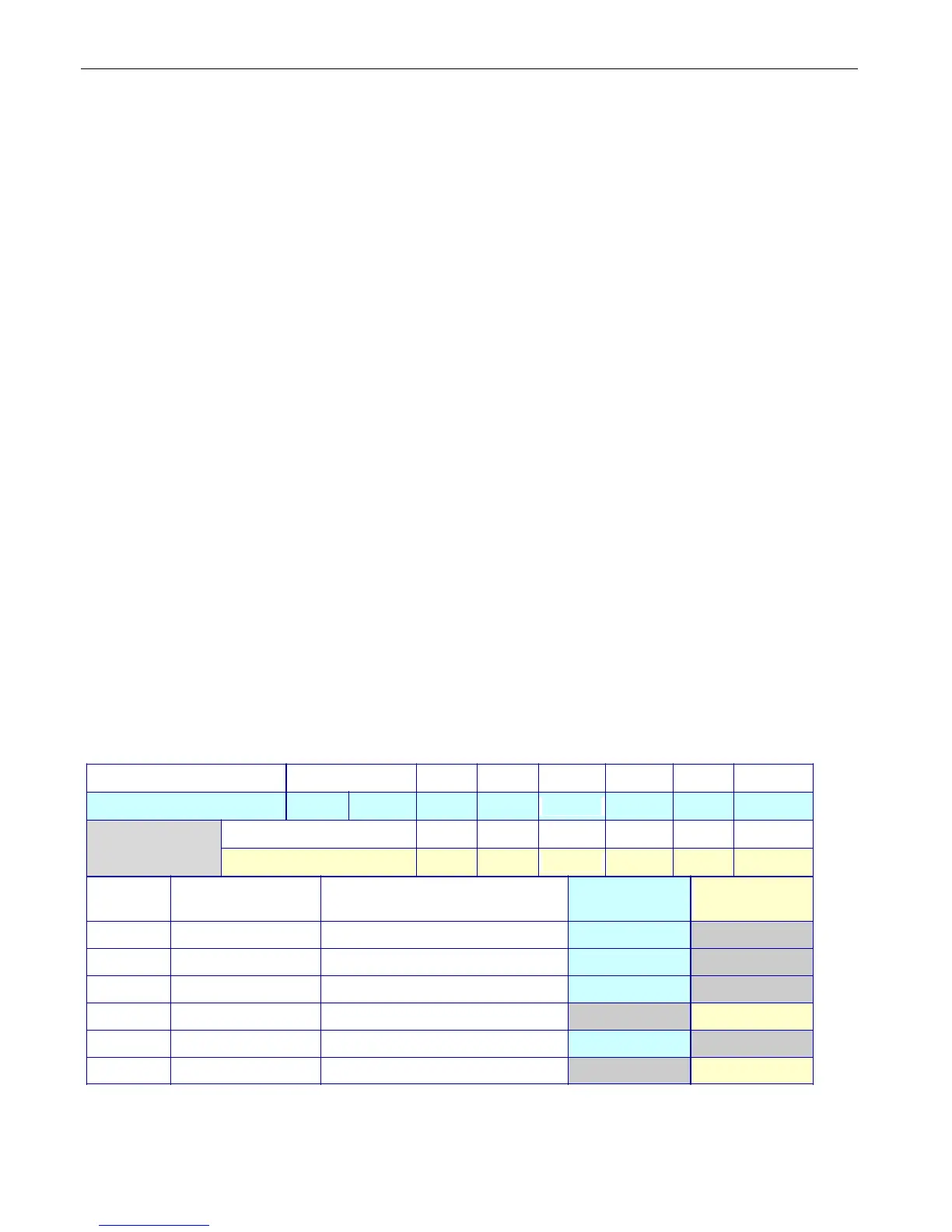
We have color coded this chart to make it easier to understand.
Match the colored rows and columns to make the settings you need based on the chart & information
below:
The green table cells show which number should be entered into the relevant CV for functions 1 and
2 to make the function respond to the numbers above them for buttons 1~6.
The pale yellow cells show additional CV numbers that can be added ONLY to functions 3 and 4 to
allocate them to buttons 7~12 if required.
The CV’s which control which CV controls function allocation for each wire are at the left with the
factory default value and the color of the wire concerned is also shown alongside them
The ~ indicates that a specific combination is not available.
Function Button number Front L Rear L 1 2 3 4 5 6
Value to use 1 2 4 8 16 32 64 128
Function Button number 7 8 9 10 11 12
Value to use 4 8 16 32 64 128
CV Default
# value
Function
Description
Value
1-6
Value
7-12
33
1 White F1/F0-F ~
34
2 Yellow F2/F0-R ~
35
4 Green F3 / Aux 1 ~
37 0 Green for Button 7+ ~
36 8 Purple F4 / Aux 2 ~
38 0 Purple for Button 7+ ~
Examples: To make function button 4 control the yellow wire, put 32 into CV34
To make function button 9 control the purple wire, put 16 into CV38