Do you have a question about the Lakeshore 620 and is the answer not in the manual?
Defines the manual's objective and coverage of the Magnet Power Supply.
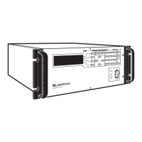
Lists the MPS models and configurations described in the manual.
Explains the meaning of safety indicators like warnings, cautions, and notes.
Provides essential safety guidelines for equipment installation.
Discusses Electrostatic Discharge hazards and necessary prevention measures.
Details procedures for safely handling ESDS components to prevent damage.
Outlines safety measures for working with liquid helium.
Addresses safety considerations during magnet quenches.
Warns about electrical hazards present inside the unit.
Covers essential pre-operation safety checks and considerations.
Summarizes critical safety precautions for operation and maintenance.
Explains various safety icons and their meanings used throughout the manual.
Introduces the chapter's content: features, specifications, and operating characteristics.
Describes the key capabilities and design aspects of the Magnet Power Supply.
Details the technical parameters and performance data for the MPS models.
Explains unique MPS operational features relevant to magnet control.
Explains the MPS's ability to source and sink current bidirectionally.
Highlights the precision and stability of the MPS current regulation.
Discusses the MPS's efficient power conversion and cooling system.
Guides users on receiving, inspecting, and unpacking the MPS unit.
Provides instructions for installing the MPS in racks or on a bench.
Specifies the recommended operating conditions like temperature and humidity.
Details power source requirements and electrical connections for the MPS.
Describes the MPS startup sequence, initial checks, and front panel indicators.
Guides connecting multiple MPS units for increased output current capability.
Covers essential checks to perform after the initial setup is complete.
Provides procedures for safely shutting down and preparing the unit for storage or shipment.
Outlines the process for returning the MPS for repair or replacement.
Introduces the chapter covering MPS operation and controls.
Describes the MPS front panel interface, buttons, and display.
Details the MPS startup sequence and initial display states.
Explains the default screen and parameters for manual operation.
Describes the display for manual persistence switch heater control.
Explains the display for automatic persistence control of magnets.
Covers accessing and navigating the MPS setup menus.
Provides a step-by-step guide for manual PSH operation.
Illustrates setting up and running an automatic PSH cycle.
Explains the dithering feature for fine current adjustment in automatic mode.
Introduces remote operation capabilities via computer interfaces.
Covers interfacing the MPS with computers using the IEEE-488 standard.
Details interfacing the MPS via the RS-232C serial port.
Lists all available remote commands for interface control.
Introduces the chapter on diagnostics and resolving MPS errors.
Lists and explains various software-detected faults and error conditions.
Provides a list of factory preset parameters and how to reinitialize them.
Details the procedure for calibrating the MPS current and voltage outputs.
Outlines tests to verify MPS functionality and accuracy.
Illustrates and defines the MPS rear panel connectors.
Shows the pinout for the IEEE-488 interface connector.
Provides wiring diagrams for serial interface cables and adapters.
Introduces optional features and accessories available for the MPS.
Explains the installation and use of the communication interface option.
Covers the Liquid Helium Level and Gaussmeter Input Card.
Describes the Persistent Switch Heater (PSH) option for magnet control.
Describes the option for controlling a second persistent switch.
Lists available accessories that complement the MPS.
Provides conversion factors for magnetic units between CGS and SI systems.
Introduces the mainframe control bus operation and its key elements.
Details serial interface configurations for RS-232C and RS-485.
Describes the physical connector and pin assignments for the serial interface.
Guides setting up the serial interface configuration via DIP switches.
Explains how to assign unique addresses for multi-drop bus operation.
Describes how to communicate with the mainframe via the serial control bus.
Provides a sample program for serial bus communication.
| Brand | Lakeshore |
|---|---|
| Model | 620 |
| Category | Power Supply |
| Language | English |