Lake Shore Model 620/622/623/647 Magnet Power Supply User’s Manual
Introduction
1-3
Front Panel: Contains a menu driven keyboard and graphic display for entry and display of results. Operating
parameters to set and monitor from the front panel (and remote interface) include:
• Output current and compliance voltage setting.
• Output current and voltage measurement.
• Status reporting.
• Output ramp programming.
• Persistent switch heater control (with optional Model 6228 Card).
• Liquid helium level monitoring (with optional Model 6226/6476 Card).
• Field Monitoring (with optional Model 6226 Card).
• Output Current Zeroing.
• Output Current Step Limiting.
Magnet inductance and compliance (di/dt = V
SET
/L) limit the output ramp programming charging current.
Program output for a constant 0.01 to 99.99 amperes per second as long as compliance is not exceeded.
Energize or de-energize the magnet at a pre-set ramp rate. Pause the ramp at any time during the ramp.
During a pause, the MPS maintains output values until the ramp continues.
Operating Ambient Temperature: 15 to 35 °C (59 to 95 °F)
Dimensions: 483 mm wide x 178 mm high x 508 mm deep (19 x 7 x 20 inches)
Weight: 43.5 kilograms (96 pounds). Rack mounting is standard.
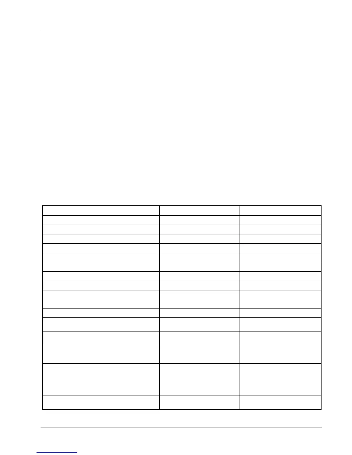
Table 1-3. Model 620/622/623 DC Output Specifications
SPECIFICATION CURRENT VOLTAGE
Digital Programming Resolution for 620/622
1 mA 1 mV
Digital Programming Resolution for 623
1.2 mA 1 mV
Digital Programming Accuracy
0.1% I
MAX
±30 mV
Digital Programming Repeatability
0.01% I
MAX
±30 mV
Electronic Resolution for 620/622
1 mA 1 mV
Electronic Resolution for 623
1.2 mA 1 mV
Electronic Accuracy
0.1% I
MAX
±30 mV
Display Resolution
1 mA 1 mV
Stability (Drift) at 25 ±1 °C: Percent of full scale
output change over 8-hours under constant line and load after
a 30 minute warm-up.
±0.005% I
MAX
±3 mV
Ripple and Noise: 10 Hz to 10 MHz at 1000 VA
20 µA rms 10 mV rms
Temperature Coefficient: Change in output per °C
after 30 minute warm-up.
±0.01% I
MAX
±3 mV
Source Effect: Line regulation for any line change within
the rated line voltage.
±0.005% I
MAX
±15 mV
Load Effect: Load regulation for a load change equal to
maximum voltage in Constant Current Mode or maximum
current in Constant Voltage Mode.
±0.01% I
MAX
±3 mV
Analog Resistance Programming Accuracy:
0 to 10 KΩ produces negative full scale to positive full scale
current or voltage output. 5 KΩ is 0 current.
10% I
MAX
3 V
Analog Voltage Programming Accuracy:
Voltage input is ±0.01 V/A, ±0.01 V/V.
1% + 100 mA
2% + 100 mV
Monitoring Output Accuracy: Voltage output is
±0.01 V/A, ±0.01 V/V.
1% + 100 mA
2% + 100 mV